
One pressure reading can answer different questions
Static pressure is the local thermodynamic pressure measured by a static tap relative to a reference. Velocity pressure represents the kinetic contribution associated with airflow speed. Total pressure combines static and velocity pressure at the same plane. Fan total pressure is the rise from fan inlet total pressure to fan outlet total pressure; fan static pressure then subtracts outlet fan velocity pressure from that rise.
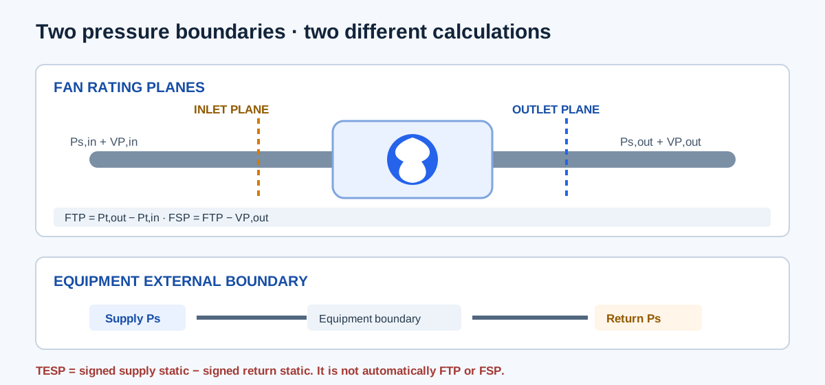
Total external static pressure (TESP) is a separate equipment-boundary quantity formed from signed supply and return static readings at the manufacturer-defined external taps. It is used to compare equipment against its own external rating or to establish a compatible duct budget. TESP is not automatically fan total pressure or fan static pressure, because the measurement planes and included components differ.
| Quantity | Definition in this project context | Typical use |
|---|---|---|
| Static pressure, Ps | Signed local gauge reading at one tap/plane | Equipment checks and pressure budgets |
| Velocity pressure, VP | Dynamic pressure from representative average velocity and local density | Convert between static and total pressure |
| Total pressure, Pt | Static pressure plus velocity pressure at the same plane | Fan plane or duct energy accounting |
| Fan total pressure (FTP) | Outlet fan total minus inlet fan total | Fan performance curve on total-pressure basis |
| Fan static pressure (FSP) | FTP minus outlet fan velocity pressure | Fan curve or efficiency on static-pressure basis |
| TESP | Signed supply/return static difference at defined equipment taps | Compare with equipment external-static data |
Select the calculation for the actual taps
The Fan Static and Total Pressure Calculator uses fan inlet and outlet rating planes, while the TESP calculator uses an equipment external boundary. Use the task whose required tap locations match the measurement. The confirmation fields preserve assumptions; they do not correct remote taps to a fan plane or authenticate the equipment limit.
- For fan pressure: record signed inlet and outlet static gauge pressure on one common reference; enter average velocity and separately established density at both fan planes.
- Enter nonnegative velocities in FPM. Use zero inlet velocity only where an open inlet/plenum genuinely has negligible average velocity.
- For equipment TESP: enter the signed return reading as nonpositive and supply reading as nonnegative according to this project’s form, with matching datum and exact external tap boundary.
- Do not move an equipment tap across a filter, coil, or accessory unless the equipment documentation includes that component in its rating boundary.
- Use the resulting FSP or FTP with a fan curve or efficiency that uses the same pressure basis.
| Task | Required readings | Key constraint |
|---|---|---|
| Fan pressure | Inlet/outlet Ps, average V, inlet/outlet density | Pressure and velocity inputs refer to fan planes |
| TESP | Supply and return signed Ps; optional rated max | Both taps match equipment external boundary |
| Duct-path budget | Compatible ASP, fitting and component losses | Do not substitute FTP/FSP for TESP without a documented conversion |
Equations, signs, and units
For the low-speed, incompressible method used by the calculator, velocity pressure is calculated from local density and area-average velocity. Inlet and outlet densities are separate inputs. Total pressure is formed at each plane before taking the fan rise. Fan static pressure subtracts outlet fan velocity pressure; the simple difference between outlet and inlet static taps omits inlet velocity pressure and is not generally fan static pressure.
For the equipment TESP form, supply static pressure is nonnegative and return static is nonpositive under its stated sign convention. Subtracting a negative return reading adds its suction magnitude. Do not enter the return suction magnitude as positive without also changing the formula basis.
VP = (ρ × V² / 2), converted to in. w.g.
Pt,in = Ps,in + VP,in; Pt,out = Ps,out + VP,out
FTP = Pt,out − Pt,in
FSP = FTP − VP,out = Ps,out − Ps,in − VP,in
TESP = Ps,supply − Ps,return
| Variable | Meaning | Unit |
|---|---|---|
| Ps | Signed static gauge pressure at a named plane | in. w.g. |
| V | Area-average velocity at that plane | FPM |
| ρ | Local air density at that plane | lbm/ft³ |
| VP | Velocity pressure | in. w.g. |
| Pt | Total pressure at the same plane | in. w.g. |
| FTP, FSP | Fan total and fan static pressure rise | in. w.g. |
| TESP | Equipment external static difference | in. w.g. |
Independent worked fan-plane example
Use a constructed peer-reproduction case: inlet static pressure is −0.602194614 in. w.g.; outlet static pressure is 1.204389228 in. w.g.; inlet average velocity is 0 FPM; outlet average velocity is 1,574.803149606 FPM; and both plane densities are 0.07491355269 lbm/ft³. Convert density to 1.2 kg/m³ and velocity to 8 m/s. Dynamic pressure is 0.5 × 1.2 × 8² = 38.4 Pa, which is 0.154162 in. w.g. using 249.08891 Pa per inch of water.
Inlet VP is zero for this open-plenum example. Inlet total pressure is −0.602194614 in. w.g.; outlet total pressure is 1.204389228 + 0.154162 = 1.358551 in. w.g. Therefore FTP = 1.358551 − (−0.602195) = 1.960746 in. w.g. and FSP = 1.960746 − 0.154162 = 1.806584 in. w.g. These independently calculated values match the calculator example after display rounding.
VPout = 38.4 Pa / 249.08891 = 0.154162 in. w.g.
FTP = (1.204389 + 0.154162) − (−0.602195) = 1.960746 in. w.g.
FSP = 1.960746 − 0.154162 = 1.806584 in. w.g.
| Result | Independent calculation | Calculator example |
|---|---|---|
| Inlet VP | 0 FPM → 0 in. w.g. | 0 for open inlet plane |
| Outlet VP | 38.4 Pa ÷ 249.08891 = 0.154162 in. w.g. | 0.154162 in. w.g. |
| FTP | 1.358551 − (−0.602195) = 1.960746 in. w.g. | 1.961 in. w.g. |
| FSP | 1.960746 − 0.154162 = 1.806584 in. w.g. | 1.807 in. w.g. |
Independent TESP example and boundary check
For an equipment-boundary example, use supply static pressure +0.45 in. w.g. and return static pressure −0.30 in. w.g. on the same datum and at the equipment-defined taps. TESP = 0.45 − (−0.30) = 0.75 in. w.g. If a documented equipment maximum were 0.50 in. w.g. for this exact condition, the entered pressure would be 0.25 in. w.g. above that maximum; the pressure comparison alone does not infer airflow or diagnose a cause.
This result is not the fan-plane example above. A fan may sit between, or farther away from, the equipment taps; intervening transitions, filters, coils, and velocity changes affect which pressure quantity is being measured. Preserve each tap’s physical location and use the manufacturer’s boundary definition before combining or comparing readings.
TESP = Ps,supply − Ps,return
TESP = +0.45 − (−0.30) = 0.75 in. w.g.
| Item | Example | Interpretation |
|---|---|---|
| Supply static | +0.45 in. w.g. | Nonnegative under the form sign convention |
| Return static | −0.30 in. w.g. | Enter signed suction, not positive magnitude |
| TESP | 0.75 in. w.g. | Measured pressure across the selected equipment boundary |
| Optional equipment maximum | 0.50 in. w.g. | Entered comparison only; exact model and condition must match |
Conclusion and limits
Static, velocity, and total pressure are related, but the readings can be combined only when their planes, signs, density basis, and gauge datum match. Fan static pressure is fan total pressure rise less outlet velocity pressure. TESP is formed at the equipment’s defined external taps and remains a different boundary quantity.
The fan-pressure relationships are explained in the cited ASHRAE fan chapter and NIST fan-system guide. The NIST guide is historical guidance, not a current code. Confirm the adopted test and rating procedure for the actual project. These arithmetic checks do not correct remote taps, certify instruments, or establish equipment compliance.
FAQs
Can I substitute TESP for fan total pressure? Not automatically. Taps and pressure planes must be compatible.
Can static pressure rise while total pressure falls? Yes. A velocity reduction can recover static pressure while fitting loss reduces total pressure.
Does the result establish a fan rating? No. It describes the entered pressure boundary and measurements.