
Start with the decision
A duct calculation is useful only when its output answers the decision in front of you. First decide whether you are checking an existing section, sizing a new section, converting a shape, budgeting pressure, interpreting a field measurement, or screening a component. A familiar formula name is not enough because the same airflow and area relationship can support different tasks.
Keep three questions separate: what is known, what must be solved, and what must be checked next. For example, known dimensions and an average velocity can solve an airflow check. They do not select a new duct size or prove that a fan can deliver that flow through the route.
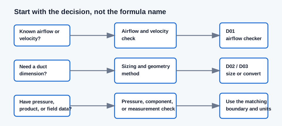
| Known or observed | Decision needed | Start with | Still outside that result |
|---|---|---|---|
| Clear dimensions and average velocity | Estimate CFM or FPM for one section | Duct Airflow and Velocity Checker | Fan operating point, fitting loss, leakage |
| Design CFM and target velocity or friction | Find theoretical or eligible duct size | Duct Size Calculator | Nominal availability, full route pressure, noise |
| Straight lengths, fittings, and component losses | Compare route pressure or available budget | Pressure-loss or friction-budget tool | A complete fan curve unless fan data is supplied |
| Product curve or field readings | Interpret a measured or catalog result | The matching product or measurement workbench | A universal coefficient or code conclusion |
Enter fields that match what you know
Use the calculator mode that matches the direction of the calculation. The field labels are part of the method: clear inside dimensions are different from outside installation dimensions; average velocity is different from a selected limit; total pressure is different from TESP; and a product curve is different from a generic pressure drop.
- For an existing round or rectangular section, use the airflow checker. Enter the clear inside dimensions and either CFM or average velocity, then choose the corresponding mode.
- For a new theoretical size, use the size calculator. Enter design CFM, then choose target velocity, friction, aspect ratio, fixed short side, or a supplied candidate schedule. Friction modes require the entered density, viscosity, and roughness instead of a hidden material preset.
- For a route or component check, keep every loss on the same airflow and pressure basis. Do not add a branch flow as if it were a series pressure loss, and do not count the same fitting through both TEL and a separate pressure entry.
Worked routing example
Suppose the known section is 12 by 8 inches with an area-average velocity of 600 FPM. The immediate question is the operating airflow, so the airflow checker is the correct first tool. Independently, clear area is 12 x 8 / 144 = 0.6667 ft², and Q = 600 FPM x 0.6667 ft² = 400.0 CFM. The result is rounded to one decimal place for this example.
If the next question is instead “what size should carry 400 CFM at 700 FPM?”, move to the size calculator. That is a new sizing task with a different target, not a second reading of the first result.
Airflow check: Q = V x A; rectangular clear area A = W x H / 144
| Question | Independent calculation | Tool output to inspect |
|---|---|---|
| What is flowing through 12 x 8 in at 600 FPM? | A = 12 x 8 / 144 = 0.6667 ft²; Q = 600 x 0.6667 = 400.0 CFM | Airflow, area, and average velocity |
| What clear area carries 400 CFM at 700 FPM? | A = 400 / 700 = 0.5714 ft² | Theoretical size and actual velocity |
| Can the selected route fit the pressure budget? | Requires straight, fitting, terminal, and equipment losses on one boundary | Pressure margin and critical path |
Read the output before moving on
Record the number with its unit, input condition, method, and boundary. A theoretical diameter is a sizing target. A measured CFM is an operating observation. A pressure margin is an arithmetic comparison at a stated airflow; it is not a fan selection or a whole-system approval.
Use the related calculator link when the output becomes the input to the next decision. The site keeps these links separate so a user can move from area and velocity to duct size, then to pressure loss, without hiding the assumptions between steps.
FAQs
Should I start with the formula I already know? Start with the decision instead. The same airflow and area relationship can check an existing section or size a new one, but the required inputs, output, and next review are different.
Can one calculator prove the whole duct design? No. Geometry, pressure, equipment, product, measurement, and code questions use different evidence. Carry the result into the next matching check.
What should I do when a required field or source value is missing? Keep the calculation qualified or unsupported until the matching project, product, or measurement information is available. Do not substitute a generic limit or hidden default.
Conclusion and limits
Choose the smallest task that answers the immediate question, then carry the result forward with its units and assumptions. This prevents a geometry check from being presented as a pressure check and prevents a preliminary size from being treated as a construction selection.
These tools do not replace current project criteria, equipment data, fitting tables, field measurements, balancing procedures, or applicable code review. Where a later step needs one of those inputs, keep it visible and perform that step separately.