
Duct-wall transfer and fan heat are different tasks
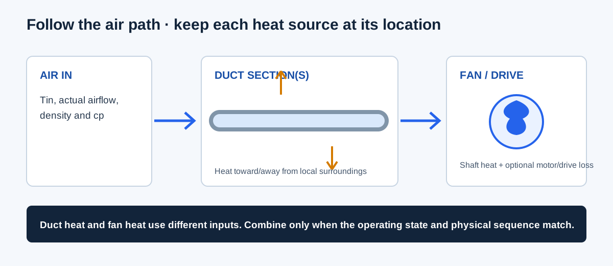
A duct heat-transfer estimate follows the air stream through duct walls and surrounding temperatures. The duct-wall tool has a single-run standard-air screen and an ordered-section mode with explicitly supplied air properties and overall U-values. A separate fan heat-gain calculation adds fan shaft power and, when both motor and drive are in the airstream, their input losses. These calculations may affect supply temperature, but their boundaries must remain distinct.
The models cover steady sensible heat only. They do not calculate latent load, condensation, leakage, solar radiation, thermal storage, fan/system operating point, or a full building load. Do not add the fan heat to a duct section unless the fan lies at that point in the same air path and the inputs describe the matching state.
| Method | Inputs | Main assumption |
|---|---|---|
| Single-run duct screen | Inlet and ambient °F, CFM, length, outside perimeter, insulation R | Standard air, constant surroundings, fixed combined film resistance |
| Ordered duct sections | Actual inlet CFM/density, compatible cp, ordered length/perimeter/U/surroundings | One steady stream; constant mass flow and properties; no mixing or leakage |
| Fan heat gain | Fan ACFM, shaft BHP, motor efficiency, drive-loss fraction, total-air density, equipment location | Fixed cp; motor and drive represented together as inside or outside the airstream |
Enter the fields for the selected method
The duct calculator changes its fields according to the selected method. Follow the order shown by the form and keep outside geometry distinct from nominal inside size. For the ordered section chain, each row is processed in airflow order and the previous outlet becomes the next inlet.
- Single-run screen: enter inlet air temperature, approximately constant surrounding temperature, standard-air CFM, run length, outside perimeter, and installed insulation R-value.
- Ordered sections: enter actual inlet ACFM and matching total-air density, a compatible constant specific heat, and one to 100 section rows with length, area-basis perimeter, overall U, and surrounding temperature.
- For each ordered section, document whether U is on the same perimeter/area basis and includes the applicable films, duct wall, and insulation. This tool does not derive U from insulation R-value.
- Fan heat: enter fan-state ACFM, fan shaft BHP, motor efficiency as a fraction, drive-loss fraction, total-air density at the same fan state, and whether both motor and drive are in the airstream.
- Use the same mass-flow and sensible-heat basis when comparing the duct and fan outputs. Do not use SCFM as the ordered-mode or fan heat ACFM input.
| Input | Unit | Boundary |
|---|---|---|
| Temperature | °F | Air, surrounding, or section boundary as labeled |
| Perimeter and section length | in and ft | Outside duct perimeter on the chosen heat-transfer area basis |
| Insulation R or overall U | h·ft²·°F/BTU; BTU/(h·ft²·°F) | Do not substitute R for overall U without applicable films/wall |
| Fan airflow and density | ACFM and lbm/ft³ | Same fan inlet/flow state |
| Specific heat | BTU/(lbm·°F) | Compatible total-air mass basis for ordered mode |
| Fan shaft power | BHP | Mechanical fan shaft, not electrical input kW |
Equations and sign conventions
For the single-run screen, outside area is perimeter times length. The overall U-value combines the entered insulation resistance and the model’s fixed 0.85 h·ft²·°F/BTU film resistance. The temperature approaches the surrounding condition exponentially with UA divided by the air-stream heat-capacity rate. Positive heat leaving the duct air is loss; negative heat leaving is gain.
The ordered model carries one mass flow and heat-capacity rate across sections. It calculates each section separately, allowing a later section to reverse the heat-transfer direction. Gross losses and gains are reported separately because they can partly cancel in the net.
Single run: A = (perimeter/12) × length; U = 1/(Rinsulation + 0.85)
C = 1.08 × CFM; Tout = Tamb + (Tin − Tamb)e^(−UA/C)
Ordered: ṁ = 60 × inlet ACFM × ρ; C = ṁ × cp
Each section: Tout = Ta + (Tin − Ta)e^(−UA/C); q = C(Tin − Tout)
| Variable | Meaning | Unit |
|---|---|---|
| A | Duct outside heat-transfer area | ft² |
| U | Overall heat-transfer coefficient on the stated area basis | BTU/(h·ft²·°F) |
| C | Air-stream heat-capacity rate | BTU/(h·°F) |
| Tin, Tout, Ta | Inlet, outlet, and surrounding temperatures | °F |
| q | Heat leaving the air stream; positive means loss | BTU/h |
| ṁ | Total-air mass flow for ordered/fan calculations | lbm/h |
Independent duct heat-loss example
Use the screen example: Tin = 120°F, Tamb = 75°F, CFM = 500, length = 50 ft, outside perimeter = 48 in, and R = 6 h·ft²·°F/BTU. Area A = (48/12) × 50 = 200 ft². U = 1/(6 + 0.85) = 0.145985 BTU/(h·ft²·°F), so UA = 29.1971 BTU/(h·°F). C = 1.08 × 500 = 540 BTU/(h·°F).
Then Tout = 75 + (120 − 75)e^(−29.1971/540) = 117.632°F when rounded to three decimals. Using the unrounded outlet, heat leaving the air is 540 × (120 − Tout) = 1,278.980655 BTU/h, displayed as 1,278.981 BTU/h. This independently reproduces the tool’s example at the stated precision. The result assumes the single-run standard-air screen and does not include fan heat.
A = 48/12 × 50 = 200 ft²
UA = 200/(6 + 0.85) ≈ 29.1971 BTU/(h·°F)
Tout = 75 + 45e^[−200/(6.85×540)] ≈ 117.632°F
q = 540 × (120 − Tout,unrounded) = 1,278.980655 ≈ 1,278.981 BTU/h
| Output | Independent calculation | Calculator example |
|---|---|---|
| Area | 200 ft² | 200 ft² from perimeter and length |
| Overall U | 1/6.85 = 0.145985 BTU/(h·ft²·°F) | Same fixed-film screening model |
| Outlet temperature | 117.632°F | 117.632°F |
| Heat leaving air | About 1,278.981 BTU/h | About 1,278.981 BTU/h |
Independent fan heat-gain example
For a separate fan example, use 8,000 ACFM, 10 BHP shaft power, 90% motor efficiency, direct drive with zero drive loss, density 0.075 lbm/ft³, and both motor and drive in the airstream. Motor/drive input equivalent = 10/0.90 = 11.111 BHP. Heat to air = 2,545 × 11.111 = 28,277.778 BTU/h. Total-air mass flow = 60 × 8,000 × 0.075 = 36,000 lbm/h. With the calculator’s fixed cp of 0.24 BTU/(lbm·°F), ΔT = 28,277.778/(36,000 × 0.24) = 3.2729°F.
The result matches the fan heat example at 3.273°F and 28,277.778 BTU/h. If the motor and drive are outside the airstream, only the fan shaft heat is added to the air in this model; motor/drive losses are assigned to the equipment space. The location switch is an explicit boundary assumption, not a way to infer where actual heat goes.
Hair = 2,545 × [10 × (1 + 0)/0.90] = 28,277.778 BTU/h
ṁ = 60 × 8,000 × 0.075 = 36,000 lbm/h
ΔT = 28,277.778 / (36,000 × 0.24) = 3.2729°F
| Quantity | Calculation | Result |
|---|---|---|
| Motor/drive input equivalent | 10 BHP / 0.90 | 11.111 HP |
| Heat to airstream | 2,545 × 11.111 | 28,277.778 BTU/h |
| Total-air mass flow | 60 × 8,000 × 0.075 | 36,000 lbm/h |
| Sensible temperature rise | Heat / (mass flow × 0.24) | 3.2729°F |
Interpret the result and choose the next check
Read every heat-transfer output with its sign, airflow state, surrounding temperature, area basis, and property assumptions. In the ordered model, inspect the section-by-section trace; net transfer can hide a larger upstream loss partly offset by downstream heat gain. Fan heat should be placed at the actual fan location when constructing an air-path sequence.
Use a separate psychrometric and condensation check when moisture matters. Verify actual insulation installation, vapor-retarder continuity, thermal bridges, leakage, and product data. These calculations are screening estimates and do not establish equipment capacity, comfort, code compliance, or measured field performance.
| Result | Not included | Next check |
|---|---|---|
| Duct outlet temperature | Humidity, phase change, leakage, storage, solar/radiant boundary | Moist-air and condensation assessment |
| Fan heat to air | VFD heat, mixed motor/drive locations, equipment heat exchange | Actual installation and power boundary |
| Net ordered heat | Local thermal bridges or unmodeled section details | Section-specific installation/property data |
Conclusion and limits
Use the duct screen for its stated standard-air, single-run assumptions, or use ordered sections when actual inlet properties and overall U-values are established. Calculate fan heat separately from matching ACFM, density, shaft power, efficiencies, and component location; combine outputs only when their sequence and state agree.
The duct screen reproduces the published NIA calculation method and its stated assumptions; the ordered heat-balance structure follows the cited DOE EnergyPlus engineering reference. The calculator does not authenticate user-entered U-values, air properties, or equipment data.
FAQs
Does fan heat equal the motor nameplate heat? No. The calculator uses the entered power and efficiency boundary for the modeled fan state.
Can a duct outlet temperature result replace a load calculation? No. It is a one-dimensional sensible heat-balance result under the entered assumptions.
What if the air properties or U-value are uncertain? Retain the uncertainty and use source-matched properties before making a design decision.