
A calculation sequence, not one sizing formula
A preliminary duct workflow starts with a documented simultaneous airflow condition, then answers separate geometry, installation, and pressure questions. A room sensible-airflow calculation or measured terminal flow can supply a CFM input, but it does not by itself establish the whole system operating state or fan duty.
Keep each decision attached to its inputs and boundary: required terminal flow, selected sizing method, clear versus outside dimensions, component and fitting data, complete route loss, and available pressure. The critical path is determined from complete compatible routes; unrelated parallel branches are not added in series.
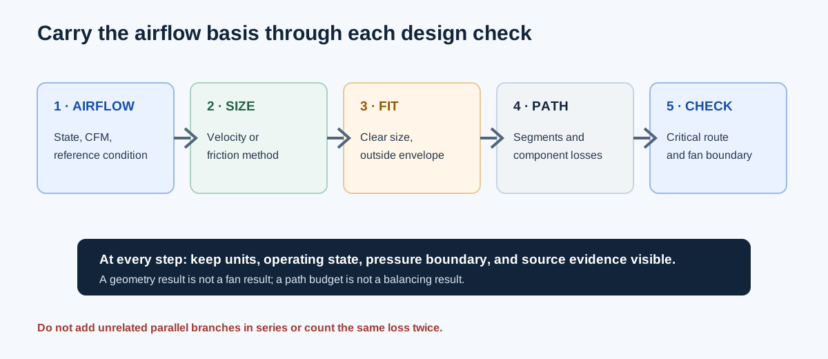
| Stage | Question | Useful output |
|---|---|---|
| Airflow basis | What simultaneous terminal or section flow is required? | CFM with state, source, and reference basis |
| Size | Which velocity or friction method and shape are being used? | Theoretical clear dimensions and method |
| Installation | Can the actual assembly fit and be connected? | Clear size, outside envelope, and layout checks |
| Pressure path | What losses occur along each complete route? | Compatible component and segment schedule |
| Equipment check | Does a matching fan total-pressure point cover the duty? | Conditional margin at the stated airflow |
Establish the airflow and select a size method
Start with design or measured airflow in CFM and identify whether the rows describe one simultaneous operating condition. For a branch system, aggregate downstream terminals for each complete state; do not sum room peaks from different states into one invented condition. If using measured velocity, use an area-average method and retain the measurement basis.
Choose target velocity when area for a selected FPM is the immediate question. Choose equal-friction sizing only when target pressure drop per length, actual density, kinematic viscosity, and internal roughness are established. Enter clear inside dimensions. A rectangular equivalent-round friction conversion and an equal-area conversion preserve different quantities.
After the theoretical dimensions are available, compare actual size candidates and installation envelopes. Include insulation, supports, flanges, transitions, access, and project clearance in the outside envelope. A calculated theoretical size does not establish stock availability or fabrication suitability.
Velocity method: A = Q/V
Round clear diameter: D = 12√(4A/π)
Friction method: solve Darcy-Weisbach with Colebrook on the circular reference
Shape and candidate checks follow their separately selected method and constraints.
| Decision | Inputs | Separate follow-up |
|---|---|---|
| Velocity size | CFM and selected FPM | Check project criterion and route pressure |
| Friction size | CFM, friction rate, density, viscosity, roughness | Check Reynolds applicability and fittings |
| Candidate selection | Actual clear sizes and outside envelopes | Verify product/fabrication and installation space |
Assemble compatible path losses
Build each route from the selected equipment pressure plane to a defined terminal or return boundary. Keep straight-duct friction, fitting loss, filter and coil drop, terminal loss, and any justified installation effect as separate contributors. Use each at its actual airflow, density, pressure definition, and source reference. Count a shared segment once on every path that includes it.
Before subtracting component losses from an equipment TESP boundary, establish which components lie outside the stated pressure taps. Fan total pressure, fan static pressure, TESP, terminal static pressure, and total-pressure endpoint requirements are not interchangeable. Do not mix a design friction rate with a complete path pressure total.
The existing path-pressure workflow can sum a single path, compare two supplied complete totals, trace one single-fan return/intake and supply schedule, or solve its constrained fixed-quadratic tree mode. These modes have different input contracts; a pressure-driven tree additionally requires a complete passive topology, compatible pressure datum, positive fixed quadratic resistances, and valid flow intervals.
| Contributor | Evidence needed | Accounting check |
|---|---|---|
| Straight duct | Length, clear size, airflow, air/surface properties | Use one method and avoid duplicating equivalent length |
| Fittings and transitions | Applicable geometry and source coefficient or measured loss | Count on the stated path at the matching condition |
| Filter, coil, terminal | Product drop at actual flow and condition | Confirm whether already inside another pressure boundary |
| Installation effect | Matching geometry, reference area, and source data | Separate from ordinary loss and include only once |
| Endpoint requirement | Defined static/velocity or total-pressure boundary | Convert to a common total-pressure reference explicitly |
Independent example: compare complete paths across one fan
Use the constructed nine-segment, 1,200 CFM schedule from a constructed nine-segment example. On the supply side, terminal 5 requires 0.10 in. w.g. endpoint total pressure and its route losses are 0.08 + 0.03 + 0.11 = 0.22 in. w.g.; its supply root requirement is 0.10 + 0.22 = 0.32 in. w.g. Other supply terminal root bounds are 0.23 and 0.20 in. w.g., so terminal 5 governs.
On the intake side, terminal 2 has boundary total pressure −0.02 in. w.g. and path losses 0.06 + 0.09 = 0.15 in. w.g. Its root ceiling is −0.02 − 0.15 = −0.17 in. w.g.; terminal 1 gives −0.13 in. w.g., so terminal 2 governs. Required fan total-pressure rise is 0.32 − (−0.17) = 0.49 in. w.g. A separately supplied constructed fan point of 0.55 in. w.g. at the same 1,200 CFM therefore has 0.06 in. w.g. arithmetic margin.
This is a schedule arithmetic example, not published fan performance or verified field data. It does not solve actual flows, adjust dampers, infer omitted branches, or interpolate a fan curve. All losses and terminal pressures must be replaced with actual compatible project evidence.
Supply root = max(terminal total pressure + path loss) = 0.32 in. w.g.
Intake root = min(terminal total pressure − path loss) = −0.17 in. w.g.
Required fan total-pressure rise = 0.32 − (−0.17) = 0.49 in. w.g.
Constructed fan-point margin = 0.55 − 0.49 = 0.06 in. w.g.
| Boundary | Governing route | Independent value | Calculator value |
|---|---|---|---|
| Supply root | Terminal 5: endpoint 0.10 + path 0.22 | 0.32 in. w.g. | 0.32 in. w.g. |
| Intake root | Terminal 2: boundary −0.02 − path 0.15 | −0.17 in. w.g. | −0.17 in. w.g. |
| Required fan total pressure | Supply root − intake root | 0.49 in. w.g. | 0.49 in. w.g. |
| Constructed matching point margin | Available 0.55 − required 0.49 | 0.06 in. w.g. | 0.06 in. w.g. |
Use the result to decide what is still unknown
If a duct route exceeds its pressure allowance, inspect the controlling segment and source inputs before resizing: airflow state, actual dimensions, fitting geometry, product drops, endpoint requirement, and equipment tap boundary. Changing a duct size alters other quantities; recalculate the affected route rather than carrying forward a stale pressure total.
A positive arithmetic margin covers only the listed duty and stated basis. A fan-system intersection, stable operating region, balanced terminal flows, acoustics, control behavior, installation effects, and adopted code requirements need their own applicable data and checks.
FAQs
Can parallel branches be summed as series losses? No. Follow complete paths and count shared trunks once; branch losses do not all occur in series through one terminal route.
Can fan static pressure or TESP replace fan total pressure in the network schedule? No. Convert pressure planes and definitions explicitly; the implemented complete-network comparison expects matching fan total pressure.
Does the calculated allowance tell a technician how to set dampers? No. A path allowance is not a damper setting, authority, noise prediction, or balancing result.
Conclusion and limits
Carry one documented airflow state through clear sizing, actual layout, complete route loss, and the pressure boundary. Keep each method and component contribution traceable, then compare a matching fan total-pressure point only at the same complete airflow basis.
The source references support the system topology and fan-pressure definitions. Example values are constructed. Current product curves, fitting data, field measurements, adopted criteria, and project code basis must be established separately.