
Condensation screening starts with the local surface
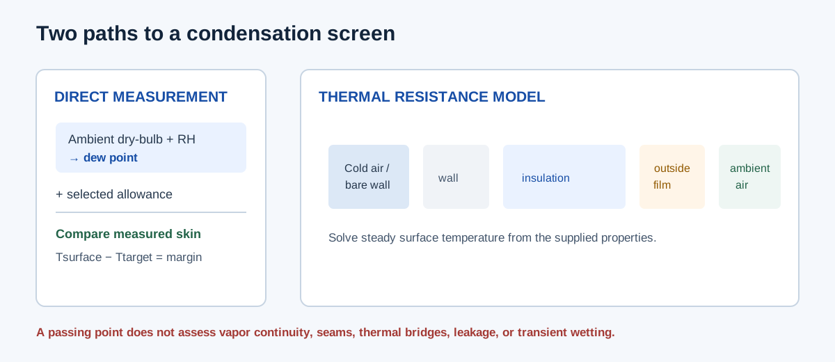
Water can condense when an exposed surface is at or below the dew point of the surrounding air. A direct screen compares a measured or prescribed outer-surface temperature with the ambient dew point plus a user-selected allowance. This answers a local surface question; it does not calculate insulation thickness, vapor diffusion, leakage, interstitial condensation, or transient wetting.
The geometry modes use a separate steady heat-transfer model to estimate the exposed insulation surface temperature from a cold duct boundary and supplied thermal properties. They support a flat face or round cylinder, with either bulk duct air or a prescribed bare outer-wall temperature as the cold boundary. An insulation result is conditional on the entered conductivity, films, wall and temperature basis.
| Mode | Known information | Result |
|---|---|---|
| Direct dew-point screen | Ambient dry-bulb/RH and measured or prescribed surface temperature | Dew/frost point, target, and surface margin |
| Flat or round installed-thickness check | Cold boundary, actual geometry, properties, and existing insulation | Modeled outer surface and margin |
| Flat or round conditional size | Same thermal inputs plus maximum search thickness | Mathematical minimum thickness within supplied range |
Enter the fields that correspond to the selected mode
The calculator contains five modes; visible inputs change with the selected mode. The text reference fields record a source or measurement basis but are not authenticated by the calculation.
- Direct screen: enter ambient dry-bulb from 35°F to 140°F, relative humidity from 1% to 100%, measured/prescribed surface temperature from 35°F to 140°F, and a nonnegative selected allowance in °F.
- Flat or round geometry: choose whether the cold boundary is bulk duct air or prescribed bare outer wall. Do not enter an already-insulated jacket temperature as the bare-wall boundary.
- Enter ambient temperature and RH, cold-boundary temperature from 35°F through ambient, nonnegative temperature allowance, positive insulation conductivity and outside film coefficient.
- Bulk-air mode also requires positive inside film coefficient and wall conductivity, plus nonnegative wall thickness. Round modes need bare outside metal diameter and preserve radial area changes.
- For a check, enter installed thickness, which may be zero. For a thickness search, enter a positive maximum search thickness; the result is theoretical and may be limited by that maximum.
| Field | Unit | Condition |
|---|---|---|
| Ambient and cold-boundary temperatures | °F | Above-freezing cooling-duct scope; cold boundary no warmer than ambient |
| Relative humidity | % | 1–100% |
| Surface allowance | °F | User-selected nonnegative screening margin, not a code minimum |
| Insulation conductivity | BTU·in/(h·ft²·°F) | Effective value over modeled temperature range |
| Film coefficients | BTU/(h·ft²·°F) | Outside combined coefficient; inside coefficient for bulk-air mode |
| Wall and insulation thickness | in | Round outside diameter is bare metal; radial geometry changes with insulation |
Dew point, surface margin, and thermal resistance equations
The calculator inverts the ASHRAE 2017 Fundamentals saturation-pressure relationship. Dew point Tdp satisfies Pws(Tdp) = (RH/100) × Pws(Tambient), with the saturation formulation switching at the water triple point as documented by the implementation. The target is dew point plus the selected allowance. Positive margin means the entered surface is warmer than that target; negative margin means it is below it.
For a flat wall, the model sums resistances per unit area. Bulk-air mode includes inside film and wall conduction; prescribed bare-wall mode bypasses those terms. Insulation resistance is thickness divided by conductivity in the calculator’s inch-based conductivity unit, and outside resistance is 1/houtside. The surface temperature is ambient minus heat flux divided by the outside film coefficient.
For a round duct, cylindrical wall and insulation resistance use logarithmic radius ratios. The method uses the bare outside metal radius plus insulation thickness for the outside area. This is a one-dimensional radial approximation, not a complete two-dimensional corner model for a rectangular duct.
Direct: Pws(Tdp) = (RH/100) × Pws(Tambient)
Ttarget = Tdp + allowance; margin = Tsurface − Ttarget
Flat: Rtotal = Rinside film + Rwall + Rinsulation + Routside film
q″ = (Tambient − Tcold)/Rtotal; Tsurface = Tambient − q″/houtside
Round insulation: Rinsulation = ln(rout/rin)/(2πkL)
| Term | Flat model | Round model |
|---|---|---|
| Cold boundary | Bulk air adds inside film and wall; bare-wall mode starts at prescribed wall temperature | Same boundary choices using inner radius/metal wall |
| Insulation resistance | Thickness / k on the entered area basis | Logarithmic radial resistance using inner and outer insulation radii |
| Outside film | Resistance per outside face area | Resistance on the outer cylindrical area |
| Surface output | Selected clear face | Outer insulation jacket |
| Not modeled | Corners, thermal bridges, moisture ingress, transient conditions | Seams, contact resistance, multi-layer and wet insulation details |
Independent direct surface example
Use ambient dry-bulb 85°F, relative humidity 70%, measured outer surface 80°F, and selected allowance 2°F. Independently inverting the cited ASHRAE 2017 saturation relation gives dew point about 74.115050°F. The selected target is 74.115050 + 2 = 76.115050°F. Surface margin is 80 − 76.115050 = 3.884950°F, displayed as 3.885°F. This matches the direct-screen example.
A positive margin means only that this measured surface exceeds this selected target for the stated ambient condition. It does not prove that the full jacket is dry, that the measurement captured cold bridges or seams, or that the selected allowance satisfies a project specification.
Tdp ≈ 74.115050°F; Ttarget = 74.115050 + 2 = 76.115050°F
Margin = 80 − 76.115050 = 3.884950°F ≈ 3.885°F
| Input/output | Value | Source or calculation |
|---|---|---|
| Ambient dry-bulb | 85°F | Entered condition |
| Ambient relative humidity | 70% | Entered condition |
| Dew point | 74.115050°F | ASHRAE 2017 saturation relation inversion |
| Selected allowance | 2°F | User input; not a universal requirement |
| Surface temperature | 80°F | Entered measurement |
| Surface margin | 3.884950°F, displayed 3.885°F | 80 − (74.115050 + 2) |
Independent flat-wall insulation example
For a constructed steady flat-face example, use ambient 85°F at 70% RH, bulk duct air 55°F, insulation conductivity 0.25 BTU·in/(h·ft²·°F), inside film h = 4, outside combined h = 1.2 BTU/(h·ft²·°F), wall thickness 0.02 in at conductivity 26 BTU/(h·ft·°F), and 1 in of insulation. Dew point is 74.115050°F and the 2°F-allowance target is 76.115050°F.
Per square foot, inside-film resistance is 1/4 = 0.25; wall resistance is (0.02/12)/26 = 0.00006410; insulation resistance is 1/0.25 = 4.0; and outside-film resistance is 1/1.2 = 0.833333 h·ft²·°F/BTU. Total R is about 5.083397. Heat flux is (85 − 55)/5.083397 = 5.901 BTU/(h·ft²). The outside surface is 85 − 5.901/1.2 = 80.082°F, leaving about 3.967°F above the selected target.
Solving the same flat-wall resistance equation for thickness gives approximately 0.432587 in at the target surface temperature of 76.115050°F. That is not a stock size or product selection. It matches the calculator’s conditional flat-wall example at its displayed precision; the illustrative constant properties do not establish a real assembly’s performance.
Rtotal = 1/4 + (0.02/12)/26 + 1/0.25 + 1/1.2 ≈ 5.083397
q″ = (85 − 55)/Rtotal ≈ 5.901 BTU/(h·ft²)
Tsurface = 85 − 5.901/1.2 ≈ 80.082°F
Conditional thickness to Ttarget: approximately 0.432587 in
| Resistance component | Calculation | Result, h·ft²·°F/BTU |
|---|---|---|
| Inside film | 1/4 | 0.250000 |
| Wall | (0.02/12)/26 | 0.000064 |
| Insulation at 1 in | 1/0.25 | 4.000000 |
| Outside film | 1/1.2 | 0.833333 |
| Total | Sum | 5.083397 |
Interpret the result and plan the next check
A direct screen is only as representative as the surface location and local ambient measurement. A jacket can be above target at one point and below it at a seam, support, penetration, or cold bridge. Geometry modes use constant steady properties and a prescribed thermal boundary; changing humidity, wind, radiation, wall/insulation properties, or construction changes the result.
Vapor-retarder continuity, air leakage, water ingress, wet insulation, mold, fire performance, code requirements, and condensation within a wall are not assessed. Check the actual product data and project criteria, then inspect the installed duct at the locations and operating conditions that matter.
| Question | This calculator provides | Separate evidence needed |
|---|---|---|
| Is this measured surface above target? | Direct margin for supplied DB/RH and surface temperature | Representative measurement locations and project allowance |
| What thickness reaches target in this model? | Conditional mathematical minimum within a search range | Product thickness, fit, seams, vapor retarder, and installed performance |
| Will the complete duct remain dry? | Not established | Bridges, penetrations, leakage, transient conditions, and vapor-control design |
Conclusion and limits
Use the direct mode when the surface temperature is already measured or prescribed. Use the flat/round thermal modes only when the cold boundary, geometry, material properties, and film coefficients are documented. Interpret the result as a conditional steady screen, not an insulation product recommendation or guarantee against condensation.
The saturation relation is ASHRAE 2017 Fundamentals SI Chapter 1, equations 5–6, as implemented in the calculator. This named historical relation is not presented as a newer edition’s psychrometric formulation. ASHRAE 2025 Chapter 23 provides the insulation and condensation-control context; the examples here use explicitly stated constructed properties rather than catalog or standard-table recommendations.
FAQs
Does a positive surface-temperature margin prove the duct will stay dry? No. Bridges, seams, penetrations, vapor control, leakage, and transients still matter.
Can I use air temperature instead of surface temperature? Only when the model or measurement supports that assumption.
Does the calculated thickness select a product? No. Check product resistance, vapor retarder, fit, seams, and installation conditions.