
What this calculation tells you
Airflow through a duct section is related to the area of the open passage and the average air velocity across that area. The Duct Airflow and Velocity Checker applies this relationship to a round or rectangular section. Depending on the selected mode, you can calculate CFM from dimensions and velocity, calculate FPM from CFM and dimensions, compare a calculated round-duct velocity with a limit you provide, or compare two rectangular sections at the same entered flow.
This is a section calculation. It does not predict the airflow a fan will deliver after system resistance changes, and it does not calculate fitting loss, leakage, sound, or a complete duct design. CFM is volume per minute at the stated air condition; FPM is feet per minute. The area must describe the clear inside air passage.
Choose the mode and enter the actual fields
Select the mode that matches the values you know. The field labels change with the mode, so confirm that every value belongs to the same duct section and operating condition.
- Round duct, CFM from diameter and velocity: enter clear inside diameter in inches and area-average or explicitly selected velocity in FPM.
- Rectangular duct, CFM from dimensions and velocity: enter clear inside width and height in inches plus average or selected velocity in FPM.
- Round duct, velocity from CFM and diameter: enter airflow in CFM and clear inside diameter in inches. The result is the section-average velocity implied by those values.
- Rectangular duct, velocity from CFM and dimensions: enter airflow and clear inside width and height.
- Round-duct velocity-limit mode: enter CFM, inside diameter, and your selected FPM limit. The comparison is only against that user-supplied criterion.
- Rectangular area-change mode: enter one CFM value and the clear width and height before and after the transition. The mode assumes unchanged airflow through both sections.
- Aspect-ratio mode: enter clear inside width and height and the maximum ratio you selected. This is a geometry comparison, not a capacity or pressure check.
| Known values | Mode result | Calculation basis |
|---|---|---|
| Round D and average V | CFM | Round clear area times velocity |
| Rectangular W and H plus average V | CFM | Clear rectangular area times velocity |
| CFM and round D | FPM | Airflow divided by round clear area |
| CFM and rectangular W and H | FPM | Airflow divided by rectangular clear area |
| Two rectangular areas and one CFM | Area ratio and two FPM values | Same entered airflow is assumed in both sections |
Formula, variables, and unit conversion
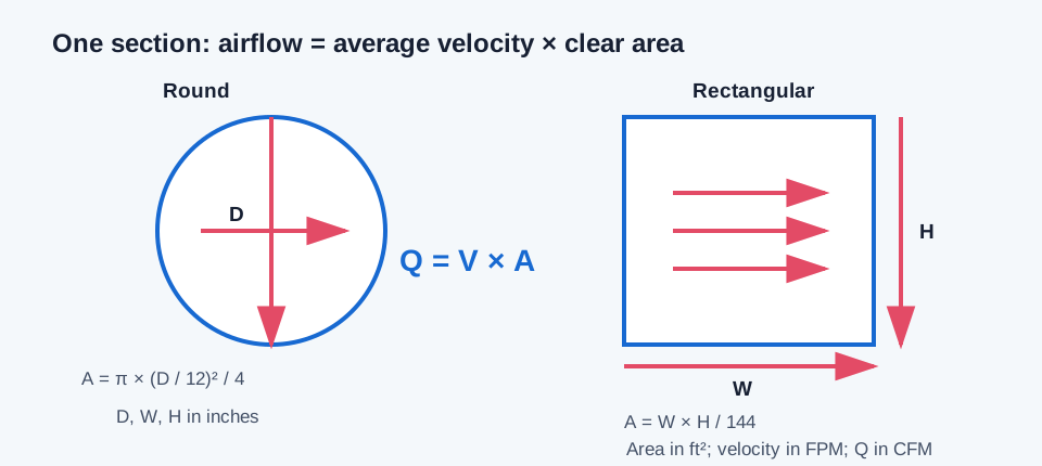
The equation uses average velocity over the full cross-section. For a circular section, D is the clear inside diameter. For a rectangular section, W and H are the clear inside width and height. When those dimensions are entered in inches, divide square inches by 144 to obtain square feet before multiplying by FPM.
The checker’s examples use one decimal place for CFM and velocity. Intermediate values may retain more precision, so a hand calculation based on displayed rounded area can differ slightly in the last digit.
Q = V × A; V = Q / A
Round: A = π × (D / 12)² / 4
Rectangular: A = W × H / 144
| Symbol | Meaning | Unit in this relationship |
|---|---|---|
| Q | Volume airflow | CFM (ft³/min) |
| V | Cross-section average velocity | FPM (ft/min) |
| A | Clear inside cross-sectional area | ft² |
| D | Round clear inside diameter | in |
| W, H | Rectangular clear inside width and height | in |
Independent worked examples
Rectangular example: a clear 12 by 8 inch section has area 12 × 8 / 144 = 0.6666667 ft². At 600 FPM, Q = 600 × 0.6666667 = 400.0 CFM. Entering the same dimensions and velocity in the rectangular CFM mode returns 400 CFM.
Round example: an 8 inch clear inside diameter has area π × (8 / 12)² / 4 = 0.349066 ft². At 600 FPM, Q = 600 × 0.349066 = 209.44 CFM, which rounds to 209.4 CFM as shown by the calculator example.
Reverse example: 400 CFM through a clear 10 inch round duct gives A = π × (10 / 12)² / 4 = 0.545415 ft² and V = 400 / 0.545415 = 733.4 FPM. This is the implied average velocity, not proof that the installed system operates at 400 CFM.
12 × 8 / 144 = 0.6666667 ft²; 600 × 0.6666667 = 400.0 CFM
π × (8 / 12)² / 4 × 600 = 209.44 CFM → 209.4 CFM
400 / [π × (10 / 12)² / 4] = 733.4 FPM
| Inputs | Independent result | Calculator example |
|---|---|---|
| 12 × 8 in, 600 FPM | 400.0 CFM | 400 CFM |
| 8 in round, 600 FPM | 209.44 CFM | 209.4 CFM |
| 400 CFM, 10 in round | 733.4 FPM | 733.4 FPM |
Interpret the result and choose the next check
A reported CFM is the result of the entered area and representative average velocity. If the velocity was measured, document the instrument, measurement section, air-density basis where relevant, and how the traverse was performed. If velocity was selected as a design input, label the result as a geometric estimate rather than a field measurement.
For a two-section area comparison at the same CFM, a smaller downstream area produces a higher calculated average velocity. That does not include pressure loss or prove that real airflow remains constant through a branch, leak, or operating system. Use the traverse tool to reduce a complete set of readings, and use a pressure-loss tool when the question is resistance.
- Use the Duct Traverse Point Layout Calculator to plan the supported point positions for a selected measurement method.
- Use the Duct Traverse Airflow Calculator to convert point readings into an area-weighted mean velocity and actual CFM.
- Use the duct sizing or pressure tools when the task is to select a size or evaluate the route, rather than infer those decisions from Q = V × A.
Conclusion and limits
For one uniform section, the relationship between CFM, FPM, and clear area is direct. Keep the dimension basis, units, and direction of the calculation explicit, and distinguish measured average velocity from a selected target or limit.
A centerline reading cannot stand in for a cross-sectional average. A section calculation also cannot establish the fan operating point, complete system pressure, acceptable sound, leakage, code compliance, or equipment capacity. Those questions require their own inputs and methods.
FAQs
Is the calculated velocity uniform everywhere in the duct? No. It is an area-average value unless a separate measurement model says otherwise.
Can the area result select the outside duct size? No. Insulation, flanges, supports, connections, and clearance need a separate envelope check.
Does a capacity result include pressure loss? No. Straight friction, fittings, components, and fan performance are separate calculations.