
What a blower-table estimate tells you
A manufacturer blower table relates a particular equipment configuration and speed tap to airflow at stated external static pressures. If measured total external static pressure (TESP) falls between two adjacent entries for that same tap, the calculator estimates airflow by linear interpolation. At an exact table pressure, it uses the listed airflow.
This method estimates airflow from model-specific product data; it does not directly measure the air stream. A traverse or other accepted field method measures airflow independently. The table estimate also does not solve the fan and system curves together, diagnose a restriction, recommend a blower tap, or establish that a target airflow is adequate.
| Method | Main input | What the result represents |
|---|---|---|
| OEM blower table | Exact model/tap data and matching measured TESP | Equipment-table airflow estimate |
| Duct traverse | Point readings, duct geometry, and method basis | Field airflow estimate from measured velocity data |
| Fan/system curve analysis | Fan curve and system resistance relationship | Predicted operating point under stated assumptions |
Match the equipment and operating condition
Before entering any values, locate the manufacturer table for the exact furnace or air-handler model and configuration. Read its footnotes because a table may specify a filter, coil, airflow mode, accessory, voltage, or pressure boundary. Confirm that the field setup matches those conditions and that the TESP measurement uses the manufacturer-defined external taps.
- Record the equipment model, blower configuration, source document and revision, page/table, and actual speed-label mapping.
- Measure supply and return external static at the correct boundary and use the TESP value in the sign convention defined for that equipment.
- Document whether the filter is installed and the applicable coil and accessory state; do not compare a different setup to the table without support.
- Enter two to 20 pressure/airflow pairs for each of one to four taps. Each row is a tap ID from 1 through 4, external pressure in in. w.g., and positive airflow in CFM.
- Enter pressures in ascending or unsorted order as convenient; the calculator sorts each tap. Duplicate pressure values within a tap are rejected.
| Field | Entry | Constraint |
|---|---|---|
| Equipment reference | Exact model, document, revision/page, table condition, tap labels | Reference note is not independently authenticated |
| Table basis | Confirm matching model, tap, condition and pressure boundary | Required before calculation |
| Measured TESP | Nonnegative in. w.g. | Must lie in every selected tap’s supplied range |
| Table point | Tap ID, pressure, airflow | Each tap needs 2–20 distinct pressure pairs |
Interpolation formula and variables
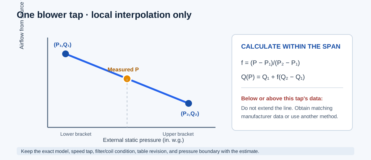
For one tap, let P be the measured TESP. Let (P₁, Q₁) and (P₂, Q₂) be the two adjacent table points that bracket it. The interpolation fraction is the share of the pressure interval from P₁ to P. Apply that fraction to the airflow difference. The calculation is local to the supplied interval; it does not establish that the manufacturer endorses linear interpolation for every table.
If P exactly matches a supplied row, the result is that row’s airflow. If P is below the lowest or above the highest pressure for any selected tap, the calculator returns an out-of-range error and does not extrapolate or clamp the result.
f = (P − P₁) / (P₂ − P₁)
Q(P) = Q₁ + f × (Q₂ − Q₁)
| Symbol | Meaning | Unit |
|---|---|---|
| P | Measured total external static pressure | in. w.g. |
| P₁, P₂ | Adjacent lower and upper source-table pressures | in. w.g. |
| Q₁, Q₂ | Airflow values at those pressures for the same tap | CFM |
| f | Linear position within the pressure interval | dimensionless |
| Q(P) | Estimated airflow at measured pressure | CFM |
Independent worked example from a historical OEM table
The cited Lennox 011Q3-105 furnace manual contains a historical table with filter-in-place airflow entries. For High speed, use 1,495 CFM at 0.30 in. w.g. and 1,450 CFM at 0.40 in. w.g. Let measured TESP be 0.35 in. w.g. The pressure fraction is (0.35 − 0.30) / (0.40 − 0.30) = 0.5. The airflow difference is 1,450 − 1,495 = −45 CFM, so estimated airflow is 1,495 + 0.5 × (−45) = 1,472.5 CFM.
Repeating the arithmetic for the other printed taps gives 1,237.5 CFM, 932.5 CFM, and 757.5 CFM at the same pressure. These figures reproduce the calculator’s historical example. They describe only the cited model and filter condition; they are not default values, a current product recommendation, or an acceptable airflow range for another system.
High tap: f = (0.35 − 0.30) / (0.40 − 0.30) = 0.5
Q = 1,495 + 0.5 × (1,450 − 1,495) = 1,472.5 CFM
| Tap label in cited table | At 0.30 in. w.g. | At 0.40 in. w.g. | At 0.35 in. w.g. |
|---|---|---|---|
| High | 1,495 CFM | 1,450 CFM | 1,472.5 CFM |
| Med-High | 1,250 CFM | 1,225 CFM | 1,237.5 CFM |
| Med-Low | 940 CFM | 925 CFM | 932.5 CFM |
| Low | 760 CFM | 755 CFM | 757.5 CFM |
Interpret the result and choose the next check
Read every estimate with its speed tap and exact or bracketing source pressures. Different taps can have different pressure spans; one tap may support the entered TESP while another does not. The calculator withholds the whole result if any supplied tap lacks an in-range bracket, rather than silently reporting only a subset.
If the question is actual delivered airflow, use an appropriate field measurement under a documented operating condition. If the question is whether the equipment can meet a design requirement, check the applicable equipment data, system resistance, heating/cooling controls, and project criteria. A larger table estimate by itself does not select the right speed setting.
| Check | Why it matters | Action |
|---|---|---|
| Equipment model and tap | Airflow tables are configuration-specific | Match the exact model and map numeric tap IDs to source labels |
| Pressure boundary | Moving taps changes measured external pressure | Use the OEM boundary and retain signed supply/return readings |
| Filter, coil, accessories | Source footnotes may include or exclude components | Match the field state or find applicable data |
| Pressure range | Linear interpolation only spans supplied adjacent points | Obtain valid source data rather than extrapolating |
| Required delivered airflow | A table estimate is not an independent measurement | Measure or apply the project’s accepted verification method |
Conclusion and limits
A blower-table calculation is useful when the exact product table and a matching TESP measurement are available. It estimates airflow at a supplied tap by exact lookup or local interpolation, with visible pressure brackets. It cannot substitute for direct measurement, a full operating-point analysis, or a project-specific equipment decision.
The numerical example is taken from a historical manufacturer manual solely to make the interpolation auditable. The method discussion also cites current program guidance for the OEM-table approach; that reference does not turn this calculator into a compliance test.
FAQs
Is airflow read from a blower table a field measurement? No. It is an estimate tied to the exact equipment table, tap, speed, and pressure boundary.
Can the table be extended beyond its last point? No. The calculator interpolates only within the supplied table range.
Can a different filter or coil condition use the same table? Only when the source explicitly supports that condition and pressure boundary.