
Available static pressure is a budget, not a rating
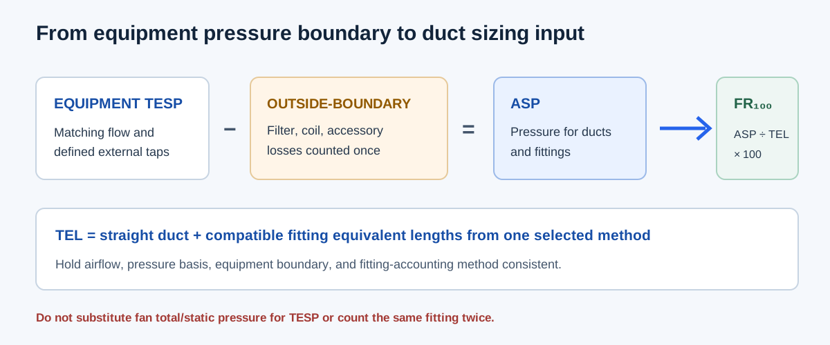
Available static pressure (ASP) is the portion of a compatible equipment external-static budget left for the duct and fitting path after applicable non-duct component losses have been deducted. Total external static pressure (TESP), fan static pressure, and fan total pressure describe different boundaries. Start with the pressure quantity the equipment or design method actually provides; do not substitute a fan pressure number for TESP without a documented relationship.
Design friction rate expresses a pressure allowance per unit of total effective length (TEL). TEL combines a compatible straight-duct length and fitting equivalent lengths from one selected method. ASP alone is not a friction rate, and a system-wide component total cannot be divided by a duct length unless the numerator and length use the same sizing basis.
| Quantity | Boundary or role | Use in this workflow |
|---|---|---|
| Fan total pressure | Pressure rise between fan inlet/outlet planes including velocity pressure | Use with a matching fan curve or total-efficiency basis |
| Fan static pressure | Fan total pressure rise minus outlet fan velocity pressure | Do not substitute for equipment TESP |
| TESP | Static-pressure difference at the equipment’s defined external taps | Starting pressure budget when data and flow condition match |
| ASP | TESP less applicable external non-duct losses outside that boundary | Pressure allowance for ducts and fittings |
| Design friction rate | ASP distributed over compatible TEL | Sizing input for the selected duct method |
Collect the required inputs in the correct order
Use the operating condition and calculation basis that match the project method. The site’s available-static-pressure check calculates TESP minus entered non-duct drops; its friction-rate function separately divides a pressure allowance by a positive length. The confirmation of applicability remains the user’s responsibility.
- Record the equipment operating airflow and whether TESP is measured or supplied by applicable manufacturer performance data.
- Confirm the equipment pressure-tap boundary and identify whether the filter, coil, or accessory is inside or outside it.
- Subtract only applicable losses not already included in that boundary. Use pressure drops that correspond to the same airflow and compatible pressure definition.
- Build TEL from straight length plus fitting equivalent lengths from one selected geometry and sizing method; do not add the same fittings again as separate pressure losses.
- Enter ASP and TEL into the design-friction-rate calculation. If the task is a single straight section instead, use that section’s own pressure drop and length.
| Entry | Basis | Common mismatch |
|---|---|---|
| TESP or applicable equipment pressure | Same equipment, flow, and external-tap boundary | Fan total or static pressure substituted without correction |
| Filter/coil/accessory drop | Same airflow and only if outside the TESP boundary | Subtracting a component already included in measured boundary |
| Fitting equivalent length | One selected fitting method and matching geometry | Mixing equivalent lengths with separately counted fitting drops |
| TEL | Straight length plus compatible fitting lengths | Using straight length alone when the method requires TEL |
Formula, units, and variable definitions
Pressure terms in the ASP subtraction are in inches of water gauge and must refer to the same operating condition and compatible pressure boundary. TEL is in feet. Multiplying the quotient by 100 expresses the result per 100 feet. The equation does not determine whether the selected pressure allowance, fitting data, or sizing method is appropriate for a particular project.
When a method defines a straight-section friction rate, the same structure applies using that section’s pressure drop and straight length. Do not add component losses to that numerator unless they are represented through the same method and length basis.
ASP = TESP − ΣΔPnon-duct,outside boundary
TEL = Lstraight + ΣLequivalent,fittings
FR₁₀₀ = ASP / TEL × 100
Units: (in. w.g. / ft) × 100 = in. w.g. per 100 ft
| Symbol | Meaning | Unit |
|---|---|---|
| TESP | Compatible total external static pressure | in. w.g. |
| ΔPnon-duct | Applicable non-duct external component loss outside TESP boundary | in. w.g. |
| ASP | Pressure available for duct and fitting path | in. w.g. |
| Lstraight | Straight duct length in the chosen sizing route | ft |
| Lequivalent | Fitting length under the selected method | ft |
| TEL | Total effective length | ft |
| FR₁₀₀ | Design friction rate | in. w.g./100 ft |
Independent worked example
Assume compatible TESP of 0.50 in. w.g. at 1,200 CFM. The matching filter loss is 0.10 in. w.g.; matching coil loss is 0.15 in. w.g.; and no other non-duct loss lies outside the pressure boundary. Then ASP = 0.50 − 0.10 − 0.15 = 0.25 in. w.g. This reproduces the site’s available-static-pressure example.
Now assume the selected fitting method gives a total effective length of 150 ft for this same path and flow basis. FR₁₀₀ = 0.25 / 150 × 100 = 0.1666667 in. w.g./100 ft, or 0.167 at three decimal places. The result is a design friction-rate input only under the stated matched-method assumption; it is not a universal maximum velocity, equipment rating, or pressure drop for each 100-foot segment.
ASP = 0.50 − 0.10 − 0.15 = 0.25 in. w.g.
FR₁₀₀ = 0.25 / 150 × 100 = 0.1666667 ≈ 0.167 in. w.g./100 ft
| Step | Inputs | Independent result | Calculator basis |
|---|---|---|---|
| Available static pressure | TESP 0.50; filter 0.10; coil 0.15; all in. w.g. | 0.25 in. w.g. | ASP = TESP − non-duct losses |
| Design friction rate | ASP 0.25; TEL 150 ft | 0.1666667, displayed 0.167 in. w.g./100 ft | FR₁₀₀ = ASP/TEL × 100 |
| Flow basis | All source data at 1,200 CFM | Required for compatibility | Not calculated by these two formulas |
Use the result to select and recheck duct sizes
Carry the calculated friction rate into the selected duct-sizing method with the design airflow and compatible fitting basis. After choosing dimensions, recheck actual velocity, fitting geometry, pressure losses, terminal requirements, and the complete critical path. If the path includes multiple branches, compare each complete route at its relevant flow rather than adding parallel branch losses as if they were in series.
If a component curve, fitting table, equipment boundary, or operating airflow is missing, the arithmetic cannot resolve the design decision. Obtain the matching source value before treating the rate as a design input. Do not use a generic friction rate simply because the calculator accepts a number.
| It establishes | It does not establish | Next check |
|---|---|---|
| A pressure-per-TEL ratio from supplied values | A required or code-approved friction rate | Confirm project method and design basis |
| Remaining ASP after entered losses | Correct component boundary or product drop | Review equipment tap locations and matched product data |
| A value for duct sizing calculations | Final pressure or airflow after size selection | Recalculate the complete path and fan/system point |
Conclusion and limits
A defensible design friction rate starts with a compatible pressure budget, subtracts only losses that belong outside the measured boundary, and uses a TEL assembled from one fitting method. Keep ASP, TESP, fan static pressure, fan total pressure, and friction rate labeled separately throughout the calculation.
The relationships align with the project-specific scope of ACCA Manual D and ASHRAE Handbook—Fundamentals Chapter 21. Exact fittings, product losses, and adopted project criteria require their own matching data; this calculation alone does not select equipment or certify a design.
FAQs
Can I divide any available pressure by duct length to get a friction rate? No. The pressure terms and TEL must describe the same sizing basis and operating condition.
Is a positive friction-rate result a universal design recommendation? No. It is the result of the entered budget, length, and assumptions.
What if a component loss or TEL value is missing? Keep the rate qualified until the matching source value is available; do not substitute a generic loss.