
These methods answer different questions
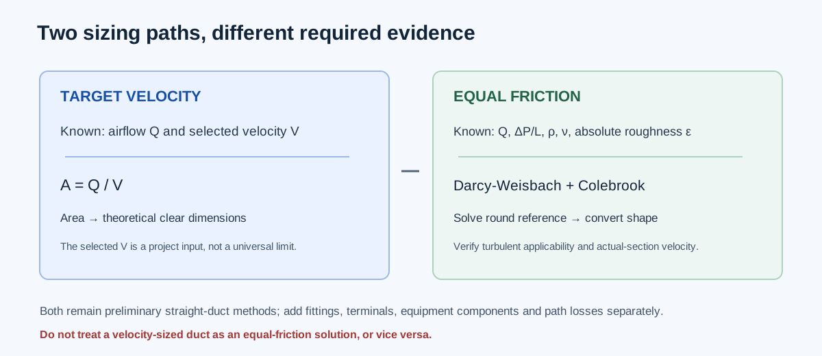
Target-velocity sizing starts with airflow and a selected average velocity, then calculates the area that would carry that flow at the selected speed. Equal-friction sizing starts with airflow, a target pressure drop per length, air properties, and roughness, then solves a circular reference diameter using Darcy-Weisbach and Colebrook. Both can produce a dimension, but only the second is constrained by the entered friction rate.
A selected velocity is a design input, not a universal code limit or a noise guarantee. An equal-friction diameter is a reference result for the stated straight-duct model, not the complete pressure loss of a route. The existing calculator can convert the friction reference to rectangular or flat-oval geometry using its specified equivalent-round method; actual section velocity remains a separate result.
| Method | Required inputs | Primary output | Still requires review |
|---|---|---|---|
| Target velocity | CFM, selected FPM, shape or ratio | Required clear area and theoretical dimensions | Project velocity criterion, nominal fit, and route pressure |
| Equal friction | CFM, in. w.g./100 ft, density, kinematic viscosity, absolute roughness | Circular reference diameter and converted shape | Turbulent applicability, component losses, and complete path |
Enter fields that belong to the selected method
For velocity mode, choose round or rectangular, enter airflow in CFM and target velocity in FPM, then enter the rectangular aspect ratio or fixed short side if that mode requires it. The calculator derives clear dimensions from area; use the actual clear section when checking the resulting velocity.
For friction mode, enter CFM, target friction rate in inches of water gauge per 100 ft, actual air density in lbm/ft³, kinematic viscosity in ft²/s, and documented absolute roughness in ft. Rectangular mode also needs a width-to-height ratio; flat-oval mode needs the fixed inside minor axis. The flow, property inputs, and surface description must represent one condition. Zero roughness is a mathematical smooth-wall input, not an inferred material preset.
The friction calculation assumes low-speed incompressible air and requires both circular reference and actual-section Reynolds numbers to remain at least 4,000. If a check falls outside the supported turbulent model, the tool withholds the size rather than extrapolating. Neither method includes fitting, transition, terminal, flex-installation, or fan operating-point calculations.
| Field | Unit | Use |
|---|---|---|
| Design airflow | CFM | Flow through the section being sized |
| Target velocity | FPM | Selected criterion for velocity mode only |
| Target friction rate | in. w.g./100 ft | Straight-duct circular-reference target for friction mode |
| Air density | lbm/ft³ | Actual stated air condition for friction mode |
| Kinematic viscosity | ft²/s | Air property for Reynolds number |
| Absolute roughness | ft | Documented internal surface input; no material is inferred |
Independent target-velocity example
For 400 CFM at a selected 700 FPM, required area is A = Q/V = 400/700 = 0.5714286 ft². The equal-area circle diameter is 12√(4A/π) = 10.2357 in. For a 2:1 rectangle, W = √(144Ar) = 12.8285 in and H = W/r = 6.4143 in. These are theoretical clear dimensions; the calculator displays about 10.2 in round or 12.8 × 6.4 in rectangle.
The velocity is exactly the selected 700 FPM before display rounding when the theoretical area is retained. Selecting an available size can change the actual velocity, and the velocity result alone says nothing about the pressure loss of fittings or the full route.
A(ft²) = Q(CFM)/V(FPM)
Round D(in) = 12√(4A/π)
For rectangle ratio r = W/H:
W(in) = √(144Ar); H(in) = W/r
| Shape | Independent value | Rounded display |
|---|---|---|
| Required area | 0.5714286 ft² | 0.571 ft² |
| Round diameter | 10.2357 in | 10.2 in |
| 2:1 rectangle | 12.8285 × 6.4143 in | 12.8 × 6.4 in |
Independent equal-friction example
Use the calculator’s illustrative case: 1,000 CFM, 0.10 in. w.g./100 ft, density 0.075 lbm/ft³, kinematic viscosity 0.00016 ft²/s, and absolute roughness 0.0003 ft. An independent Darcy-Weisbach calculation with the Colebrook relation gives a circular reference diameter of about 13.646 in, reference velocity about 984.609 FPM, Reynolds number about 116,631, and Darcy friction factor about 0.018848. This reproduces the entered friction rate; it is an example, not a recommended design target.
For a 2:1 rectangular equivalent-round conversion, ASHRAE Equation 25 gives a theoretical clear section about 17.915 × 8.958 in. Its actual-area velocity is about 897.299 FPM, distinct from the circular reference velocity of about 984.609 FPM. The equal-friction method preserves the stated reference relationship; it does not mean the converted rectangle has the same area or velocity.
Darcy-Weisbach: ΔP/L = fD ρV²/(2D)
Colebrook: 1/√fD = −2log10(ε/(3.7D) + 2.51/(Re√fD))
Rectangular equivalent: De = 1.30(WH)^0.625/(W+H)^0.25
| Quantity | Independent result | Calculator result |
|---|---|---|
| Circular reference diameter | 13.64597 in | 13.64597 in |
| Circular reference velocity | 984.609 FPM | 984.609 FPM |
| Circular Darcy friction factor | 0.0188482 | 0.0188482 |
| 2:1 rectangular section | 17.91545 × 8.95772 in | 17.91545 × 8.95772 in |
| Actual rectangular velocity | 897.299 FPM | 897.299 FPM |
What to check after sizing
Compare the result with the actual clear dimensions, insulation and outside envelope, available size list, aspect or installation limits, and the governing velocity or friction criterion. Then build complete supply/return path pressure budgets with fittings, terminals, filters, coils, and other applicable losses counted once at compatible boundaries.
A friction-based size does not automatically satisfy a velocity or acoustic criterion. A velocity-based size does not prove an equal-friction result. If a project uses both constraints, evaluate them independently against constructible candidates and the actual system data.
| Check | Question |
|---|---|
| Constructibility | Do clear and outside dimensions fit with insulation, supports, access, and connections? |
| Velocity | Does the actual selected size meet the project criterion at this airflow? |
| Pressure | Are straight friction and fitting/component losses represented on compatible bases? |
| Equipment | Does the complete critical path fit the available pressure at the actual fan point? |
FAQs
Does equal friction mean every duct section has the same pressure loss in the installed system? No. The sizing correlation establishes a straight-duct reference under its assumptions; fittings and components add separate losses.
Can the target velocity be treated as a code maximum? No. It is an entered design criterion. Use the governing project requirements and assess sound and system pressure separately.
Why can rectangular actual velocity differ from the round-reference value? The shape conversion follows an equivalent-round friction correlation, not equal area. Actual velocity uses the rectangular section’s actual clear area.
Conclusion and limits
Use target velocity when the question is the area associated with a selected average speed. Use equal-friction sizing when the straight-duct pressure-rate basis and air/surface properties are established. Record which method produced the dimension and perform the remaining construction and system checks separately.
The existing calculator uses Darcy-Weisbach/Colebrook for a circular reference and the cited ASHRAE equivalent-round relationship for noncircular shapes. It does not provide a universal velocity limit, nominal fabrication size, fitting table, or complete Manual D design.