
A VAV candidate must pass every required state
A VAV terminal can pass cooling and fail the minimum ventilation, neutral, or heating state because controller range, pressure, coil capacity, discharge temperature, or catalog sound changes with operating condition. Selection from nominal inlet size or one airflow misses those failures.
The calculator evaluates cooling, neutral, and heating states using primary ventilation airflow, sensible loads, controller K√signal range, pressure, reheat/coil capacity, and exact catalog rating rows. It does not turn outdoor-air volume directly into primary terminal airflow.
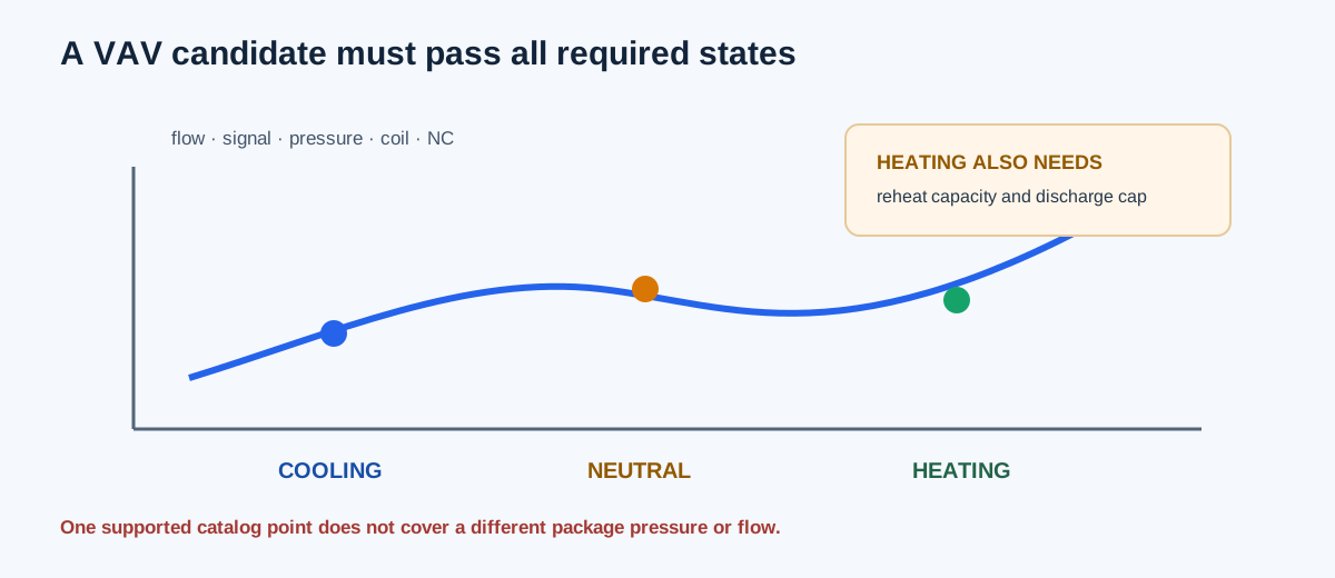
| State | Typical checks |
|---|---|
| Cooling | Load airflow, sensor, pressure, coil capacity, radiated/discharge NC |
| Neutral/minimum | Primary ventilation flow, controller range, pressure and acoustic point |
| Heating | Heating airflow, reheat capacity, discharge temperature, pressure and acoustic point |
Enter the actual control and package contract
Document controller/sensor, terminal, coil, acoustic, pressure, and project control sequence. Enter zone loads and temperatures, primary ventilation already resolved by the ventilation analysis, package pressure at each state, selected discharge and noise limits, and exact candidate rows at the actual rated conditions.
The candidate table must identify flow, bare-terminal pressure, minimum terminal pressure, coil pressure drop, capacity, radiated NC, and discharge NC. The calculator does not interpolate a missing pressure point or transfer a sound rating from another package differential pressure.
| Step | Record |
|---|---|
| 1 | Zone loads, temperatures, density, cp |
| 2 | Primary ventilation and state pressure |
| 3 | Controller K factor, signal range, terminal limits |
| 4 | Exact candidate ratings for each state flow |
| 5 | Review all state margins and support flags |
Independent cooling and heating example
Use cooling load 17,280 Btu/h, primary air 55°F, cooling room 75°F, density .075 lbm/ft³, cp .24 Btu/lbm·°F, and candidate 1 with K = 904, minimum flow 90 CFM, maximum 900 CFM, and maximum package pressure 2 in. w.g. Cooling airflow is 17,280/(1.08×20) = 800 CFM. Heating airflow at a 90°F discharge cap is 12,960/(1.08×35) = 342.857 CFM for zone heat alone, but the implemented heating state includes 600 CFM cold-primary reheat airflow from the stated control/ventilation condition.
Required reheat includes both the zone heating load and warming the cold primary air to the 70°F room condition: 12,960 + 1.08×600×(70−55) = 22,680 Btu/h. The resulting heating discharge is 70 + 12,960/(1.08×600) = 90°F. This is why the cold-primary control state must be documented rather than replacing the state with a zone-load-only estimate.
Sensible cooling airflow = 17,280/(1.08×(75−55)) = 800 CFM
Controller sensor minimum = 904×√0.01 = 90.4 CFM
Configured minimum = max(600 ventilation, 90.4 controller) = 600 CFM
Worked heating airflow = 600 CFM
Required reheat = 12,960 + 1.08×600×(70−55) = 22,680 Btu/h
Heating discharge temperature = 90°F
| Result | Independent or worked-example value | Calculator display |
|---|---|---|
| Cooling airflow | 800 CFM | 800 CFM |
| Sensor minimum | 90.4 CFM | 90.4 CFM |
| Configured minimum | 600 CFM | 600 CFM |
| Heating airflow | 600 CFM | 600 CFM |
| Heating reheat capacity | 22,680 Btu/h | 22,680 Btu/h |
| Heating discharge | 90°F | 90°F |
Read ratings at the exact state points
A rating point is supported only when its candidate ID, airflow, package pressure, and acoustic basis match the requested state. A candidate can have enough maximum airflow and still fail the heating flow cap, minimum controller signal, coil capacity, discharge temperature, pressure margin, or catalog NC.
Review candidate support and margins state by state. A positive cooling margin does not carry into neutral or heating. If a state lacks an exact rating row, keep it unsupported rather than interpolating a product curve that the source did not provide.
| Finding | Meaning |
|---|---|
| Sensor minimum fails | Controller cannot support the requested low flow on entered K/signal |
| Pressure point unsupported | No exact product/package rating at that state |
| Coil capacity margin negative | Entered coil capacity is below required output |
| Discharge temperature fails | Heating state exceeds entered maximum |
| All states pass | Entered envelope is supported; installation and control review remain |
FAQs
Can outdoor-air CFM be used directly as VAV primary airflow? No. Primary airflow comes from the resolved ventilation and control condition. Can a terminal catalog NC rating be moved to another pressure? No. Match the exact package rating. Does a pass select the controller and coil? No; signal calibration, actuator, sequence, reheat, access, leakage, and installation still require review.
The calculator does not authenticate current product data, solve the full duct/fan system, select a ventilation standard, or establish code compliance. Replace teaching rows with the exact submittal.
Conclusion and limits
Select a VAV terminal across cooling, neutral/minimum, and heating states. Keep ventilation, load airflow, controller range, package pressure, coil capacity, discharge temperature, and catalog acoustic data distinct at each state.
The calculator provides a transparent envelope comparison from the entered rows. It does not replace the actual terminal submittal, control sequence, fan/system analysis, or commissioning.