
A terminal selection has several separate decisions
A grille, register, or diffuser must fit the airflow and opening while satisfying the product-specific pressure, sound, throw, and installation conditions that matter for the application. Free area describes the open passage through a face; gross face area describes the overall envelope; core or neck area may be the manufacturer’s velocity basis. These areas are not interchangeable.
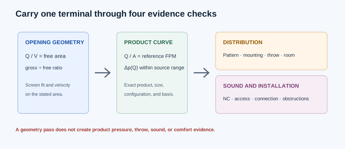
The workbench has geometry modes for a first screen and a product-curve mode for one identified model, size, and configuration. A geometry result can tell you how large an opening would be at a selected velocity. It cannot create a throw, NC, or pressure rating for an unspecified product.
| Quantity | What it describes | What it cannot replace |
|---|---|---|
| Gross face area | Overall face envelope | Free, core, or neck area |
| Free area | Open passage through a grille or register face | A product pressure curve or acoustic rating |
| Core or neck area | A manufacturer’s stated velocity reference | Gross-face or free-area velocity |
| Throw | A product/test condition’s jet reach | A generic room-distance or comfort guarantee |
| NC or sound data | A stated product/test acoustic condition | The sound level of the complete installed system |
Choose the calculation mode and enter the real inputs
Use the gross-area mode when you know airflow, a selected face velocity, and the actual product free-area ratio. Use the free-area mode when only the required open area is being screened. Use the connection mode to compare the clear areas of the duct and terminal. Use the terminal-size mode only for a geometric equivalent-diameter comparison.
For a product curve, identify the exact manufacturer, model, nominal size, configuration, source page or revision, pressure definition, and area basis. Confirm that every airflow/pressure row belongs to the same product and condition. Enter positive pressure-loss magnitude when the source prints negative static pressure. The calculator uses an exact point or piecewise-linear interpolation between adjacent entered points and refuses extrapolation.
| Task | Enter | Result |
|---|---|---|
| Free and gross area | Airflow, selected face velocity, free-area ratio | Required free area and gross face area |
| Connection check | Airflow, duct clear area, terminal clear area | Duct and terminal clear-area velocities |
| Geometry comparison | Duct and terminal equivalent diameters | A dimensional comparison only |
| Product curve | Exact product data, reference area, limits, curve points | Source-bounded pressure and reference-area velocity |
Independent geometry example: free area and gross area
Suppose a return grille must pass 400 CFM at a selected 500 FPM face velocity, and the actual grille has a documented free-area ratio of 0.50. Required free area is A_free = Q/V = 400/500 = 0.800 ft². Gross face area is A_gross = A_free/ratio = 0.800/0.50 = 1.600 ft². This is an opening screen; the product still needs its own pressure, sound, mounting, and maintenance review.
If the ratio is only an estimate, the gross-area result carries that uncertainty. A different grille pattern can have a different free-area ratio at the same nominal width and height. Do not replace a manufacturer’s stated free area with a catalog face dimension.
A_free = Q / V_face = 400 CFM / 500 FPM = 0.800 ft²
A_gross = A_free / free-area ratio = 0.800 / 0.50 = 1.600 ft²
| Quantity | Independent value | Calculator display |
|---|---|---|
| Required free area | 400/500 = 0.800 ft² | 0.800 ft² |
| Gross face area | 0.800/0.50 = 1.600 ft² | 1.600 ft² |
Independent connection and product-curve examples
For a 400 CFM connection with a duct clear area of 0.667 ft² and terminal clear area of 0.800 ft², the duct velocity is 400/0.667 = 599.700 FPM and the terminal velocity is 400/0.800 = 500.000 FPM. The difference is a geometry comparison; it does not calculate the terminal pressure drop.
For the workbench’s historical Titus 350R/350F/350R-SS 6×6 in example, use 114 CFM, a 0.19 ft² core reference area, and an exact source pressure point of 0.073 in. w.g. The independent velocity is 114/0.19 = 600 FPM. Against a selected 0.08 in. w.g. pressure limit and 650 FPM velocity limit, the margins are 0.007 in. w.g. and 50 FPM. The source point is reproduced for arithmetic checking; it is not a current product or installed-performance certification.
V_duct = 400 / 0.667 = 599.700 FPM
V_terminal = 400 / 0.800 = 500.000 FPM
V_core = 114 / 0.19 = 600 FPM
Pressure margin = 0.080 − 0.073 = 0.007 in. w.g.
Velocity margin = 650 − 600 = 50 FPM
| Check | Independent value | Calculator display |
|---|---|---|
| Duct clear-area velocity | 599.700 FPM | 599.7 FPM |
| Terminal clear-area velocity | 500.000 FPM | 500.0 FPM |
| Product pressure point | 0.073 in. w.g. | 0.073 in. w.g. |
| Product reference velocity | 600 FPM at core area | 600 FPM at core area |
| Selected pressure margin | 0.007 in. w.g. | 0.007 in. w.g. |
Use throw, pressure, and sound data together
A diffuser layout needs the actual product pattern, mounting, ceiling or room condition, airflow at each outlet, throw basis, pressure loss, and acoustic convention. The diffuser layout calculator uses exact supported catalog points for its minimum and maximum operating states. It does not interpolate a missing catalog flow, substitute per-side flow for total outlet flow, or turn a nominal neck size into a throw rating.
For grilles and registers, confirm the product’s free area and pressure data at the intended flow, then review sound and room placement. For return openings, check whether the product pressure and face-velocity basis matches the return application. A terminal that fits the opening can still be unsuitable because of pressure, noise, throw, pattern, or access.
| Review | Required evidence |
|---|---|
| Geometry | Clear opening, gross dimensions, free/core/neck area definition |
| Pressure | Exact product curve, airflow, pressure definition, and test basis |
| Distribution | Pattern, mounting, room dimensions, throw basis, and operating states |
| Sound | Product NC or sound data with its stated absorption and test condition |
| Installation | Connection, access, damper, lining, obstructions, and maintenance clearance |
FAQs
Is free area the same as face area? No. Free area is the open part of the face. The ratio between free and gross area is product-specific and must be used on the same stated basis.
Can a target FPM select a diffuser? No. It can screen the opening or reference velocity. Throw, pressure, NC, pattern, and installation conditions still require matching product data.
Can a product curve be extended above its last point? No. The workbench withholds numeric pressure outside the entered range. Add supported product data or select a different documented product condition.
Does a passing pressure and velocity screen prove the room will be comfortable? No. The result does not model obstructions, asymmetric jets, room loads, occupied-zone velocities, actual drafts, or whole-room acoustics.
Conclusion and limits
Use geometry modes to make the opening and connection understandable, then use exact product evidence for pressure, throw, sound, and installation. Keep free, gross, core, and neck areas labeled at every step, and compare all required operating states before selecting a terminal.
The cited product examples and calculator tables support the displayed arithmetic only. They do not establish a universal velocity limit, current availability, code compliance, acoustic acceptance, or an installed terminal selection.