
Two ways to represent a fitting loss
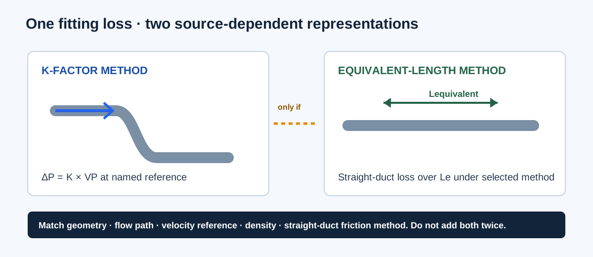
A dimensionless fitting K-factor expresses a pressure loss as a multiple of velocity pressure at a defined reference section. Equivalent length expresses that same fitting through the pressure loss of a selected straight-duct method over a stated length. Both approaches can be useful, but they are not interchangeable inputs and neither value is universal for every elbow, tee, wye, transition, or flow split.
The fitting’s geometry, angle, radius, area ratio, branch or through-flow path, airflow, density, Reynolds regime, and source convention all matter. A K-factor from one reference velocity cannot be added directly to an equivalent length, and an equivalent length from one method cannot be transferred to a different duct size or fitting arrangement without a documented conversion.
| Representation | Core relationship | Required source context |
|---|---|---|
| K-factor | ΔP = K × VPreference | Reference area/velocity, density basis, path, geometry, and coefficient source |
| Equivalent length | ΔP = straight-duct loss for Lequivalent | Straight-duct method, duct size, friction basis, fitting geometry and path |
| Total effective length | TEL = straight length + ΣLequivalent | One compatible equivalent-length method across the path |
| Mixed schedule | Sum pressure losses only when references are compatible | Each row’s local velocity pressure and source definition |
Identify the path and source before entering values
The site’s fitting pressure schedule accepts rows with a quantity, local flow/area/density, and a supplied coefficient. Its total effective-length and pressure-loss tools use different input contracts. Select the tool based on the data you actually have rather than forcing a coefficient into a length field.
- Name the fitting and path: elbow, branch, tee, wye, transition, inlet, outlet, through path, or branch path.
- Record the source’s reference velocity or area, coefficient conditions, geometry ratios, angle, radius, and flow split. A branch coefficient is not automatically a through coefficient.
- For a K schedule, enter velocity pressure inputs that belong to each fitting’s reference section. The calculator can report an equivalent common reference only when its reporting option and reference are explicitly supplied; that is a reporting conversion, not a new universal K.
- For TEL, use equivalent lengths from one selected method and matching duct/fitting geometry. Do not add those fittings again as separate K-based pressure drops.
- If the matching table or coefficient is missing, the numeric pressure loss or equivalent length remains unsupported. Do not invent a generic elbow or tee value.
| Input | What to document | Why it matters |
|---|---|---|
| Fitting identity | Type, path, angle, radius, branch/through designation | Different flow paths have different losses |
| Geometry | Area ratio, size, aspect or centerline dimensions | Coefficients are not nominal-size constants |
| Flow basis | Airflow and density at the reference section | Velocity pressure changes with flow, area, and density |
| Method | K table or equivalent-length method and revision | Values from different methods cannot be mixed silently |
| Interactions | Nearby fittings, transitions, and shared sections | Close-coupled assemblies may need a combined source |
Formula, variables, and a documented conversion boundary
For a K-factor entry, calculate velocity pressure from the selected local velocity and density in consistent units, then multiply by K. The site fitting schedule keeps this local reference with the row. For an equivalent-length entry, the selected straight-duct friction method supplies the pressure drop for that length. The conversion between the two representations is valid only when the straight-duct friction factor, hydraulic diameter, velocity reference, and fitting source are all compatible.
Do not add K values that use different velocity pressures. If two fittings use different local reference sections, first calculate each physical pressure loss separately. Only a documented common-reference conversion may support a reported coefficient sum, and that sum must not be reused as a new coefficient for another geometry or operating point.
ΔPfit = K × VPref
VPref = ρV² / 2, with consistent unit conversion
TEL = Lstraight + ΣLequivalent
A matched conversion requires ΔPfit = ΔPstraight(Lequivalent) under the same method and basis
| Variable | Meaning | Unit or basis |
|---|---|---|
| K | Dimensionless fitting-loss coefficient | Source-defined reference |
| VPref | Velocity pressure at the named reference section | in. w.g. after unit conversion |
| ρ | Air density at that reference section | Consistent mass/volume basis |
| V | Representative velocity at that section | ft/s or FPM, consistently converted |
| Lequivalent | Straight-duct length representing the fitting | ft under one selected method |
| ΔPfit | Fitting total-pressure loss in the selected model | in. w.g. |
Independent worked pressure example
Use a constructed, explicitly labeled coefficient example rather than a standard fitting value: a geometry-matched fitting source supplies K = 0.50 for a reference section. At that section, use velocity V = 1,000 FPM and density ρ = 0.075 lbm/ft³. Convert velocity to 16.6667 ft/s. In customary engineering units, dynamic pressure is ρV²/(2gc), with gc = 32.174 lbm·ft/(lbf·s²): 0.075 × 16.6667² / (2 × 32.174) = 0.32376 lbf/ft². Since 1 in. w.g. is approximately 5.20249 lbf/ft², VP ≈ 0.06223 in. w.g. Therefore ΔPfit = 0.50 × 0.06223 ≈ 0.03112 in. w.g.
This arithmetic demonstrates how a supplied K becomes a pressure loss; K = 0.50 is not presented as a universal elbow or tee coefficient. To express the same 0.03112 in. w.g. as equivalent length, the straight-duct method would need to supply a pressure loss per foot at the same airflow, hydraulic diameter, roughness, density, and friction basis. Without that matched straight-duct source, no numeric equivalent length is claimed.
V = 1,000/60 = 16.6667 ft/s; gc = 32.174
VP ≈ [0.075 × 16.6667² / (2 × 32.174)] / 5.20249 = 0.06223 in. w.g.
ΔPfit = 0.50 × 0.06223 ≈ 0.03112 in. w.g.
| Item | Value | Status |
|---|---|---|
| Source coefficient | K = 0.50 | Constructed input for arithmetic only |
| Reference velocity | 1,000 FPM | At the named reference section |
| Density | 0.075 lbm/ft³ | Constructed total-air basis |
| Velocity pressure | About 0.06223 in. w.g. | Independent unit conversion including gc |
| Fitting loss | About 0.03112 in. w.g. | K × local velocity pressure |
| Equivalent length | Not calculated | Requires a matched straight-duct friction source |
Use the chosen representation without double counting
A pressure schedule can sum straight losses, fitting losses, filter/coil losses, terminals, and other compatible components when every row uses the same airflow and pressure reference. A TEL-based duct-sizing workflow instead represents fittings through equivalent lengths and applies a friction basis. Do one accounting pass, then verify that the resulting complete path does not include the same fitting twice.
For a branch network, compare complete paths at their assigned airflow. Shared trunk losses appear once on each downstream path, while parallel branches are not added in series. If a source gives a combined assembly loss for close-coupled fittings, use that combined value instead of adding individual coefficients that already include interaction.
| Known data | Preferred next step | Avoid |
|---|---|---|
| Geometry-matched K and local velocity basis | Calculate each fitting pressure loss | Adding K values from different reference sections |
| Equivalent lengths from one method | Build TEL and apply the method’s friction basis | Adding those fittings again as K losses |
| Only fitting name and nominal size | Obtain the matching source table | Inventing a universal coefficient |
| Close-coupled fitting assembly data | Use the combined source loss if applicable | Summing individual values that already include interaction |
Conclusion and limits
K-factor and equivalent length are two representations of fitting resistance, each tied to its own reference and source method. Keep geometry, path, flow, density, velocity reference, and fitting interaction visible. When a matched source is missing, the correct result is to request that source rather than create a portable number.
ASHRAE Handbook—Fundamentals Chapter 21 and ACCA Manual D describe the duct-design context and the need for method-matched fitting data. The site’s pressure schedule preserves supplied row references; it does not create a universal fitting database or certify a completed duct design.
FAQs
Can I use a K value from another fitting geometry? No. Coefficients depend on the fitting, flow ratio, construction, and reference velocity.
Does equivalent length equal a physical duct length? No. It is a pressure-loss representation under a selected method.
Can I enter both equivalent length and the fitting pressure loss? Not for the same fitting loss; that would double count it.