
A component pressure result belongs to one product condition
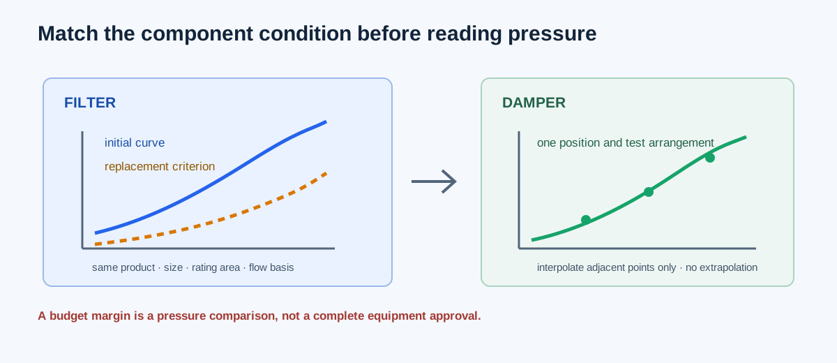
Filter and damper pressure drop depends on the exact product, size, reference area, airflow, loading or blade condition, test arrangement, and pressure definition. A MERV label, nominal duct size, or damper angle by itself cannot create a pressure curve. The calculator accepts user-entered source points so the condition remains visible and traceable.
The filter method also keeps a selected replacement resistance separate from the entered initial curve. That value is a project or manufacturer criterion for a later condition; it is not a predicted loaded curve, a service-life estimate, or a structural pressure limit.
| Item | Filter | Damper |
|---|---|---|
| Product state | Exact model, size, depth, clean/loaded condition | Exact model, size, blade position/action, test arrangement |
| Curve coordinate | CFM or catalog reference FPM | CFM or catalog reference FPM |
| Area | Catalog reference face area | Specified test/reference area |
| Pressure | Same static-pressure loss definition | Same pressure definition and direction |
| Extra criterion | Replacement resistance | Application velocity or position limit |
Enter the curve and choose the interpolation basis
Enter the product and source reference, flow on the curve’s stated rating basis, catalog reference face area, application velocity limit, curve coordinate basis, interpolation method, pressure budget, and at least two increasing curve rows. Use CFM when the source’s first column is airflow or FPM when it is reference face velocity. The calculator derives velocity as Q/A and checks it against the selected limit before reading the curve.
Linear interpolation connects adjacent points on ordinary axes. Log-log interpolation connects adjacent positive points on logarithmic axes. Neither option fits a universal exponent or permits extrapolation. If the manufacturer specifies a different method or supplies a nearby point, follow that source rather than treating the calculator’s interpolation choice as a product law.
| Step | Input | Reason |
|---|---|---|
| 1 | Product, size, condition, source and pressure boundary | Prevents mixing rows from different tests |
| 2 | Flow, face area and application velocity limit | Defines the rating coordinate and screening condition |
| 3 | Curve basis and interpolation method | Makes the coordinate and calculation explicit |
| 4 | Pressure budget and complete source rows | Provides a visible margin and avoids invented endpoints |
| 5 | Replacement resistance for filters | Keeps service-condition comparison separate |
Independent filter example: initial curve and replacement headroom
Use the dated AAF PerfectPleat HC M8 24×24×2 in example with 1,600 CFM on the source rating basis, a 4 ft² reference face area, a 625 FPM application limit, an initial curve of 300 FPM/0.12, 500 FPM/0.23, and 625 FPM/0.34 in. w.g., a 0.50 in. w.g. component budget, and a selected 1.00 in. w.g. replacement resistance. Reference velocity is 1,600/4 = 400 FPM, between the first two points.
The linear fraction is (400−300)/(500−300) = 0.5. Initial pressure is 0.12 + 0.5 × (0.23−0.12) = 0.175 in. w.g. Current-curve margin is 0.50−0.175 = 0.325 in. w.g. Replacement-condition margin is 0.50−1.00 = −0.500 in. w.g.; the selected budget covers the initial curve but not the selected replacement criterion.
V_face = Q/A = 1,600/4 = 400 FPM
t = (400−300)/(500−300) = 0.5
P_initial = 0.12 + 0.5(0.23−0.12) = 0.175 in. w.g.
Current margin = 0.50−0.175 = 0.325 in. w.g.
Replacement margin = 0.50−1.00 = −0.500 in. w.g.
| Result | Independent value | Calculator display |
|---|---|---|
| Reference face velocity | 400 FPM | 400 FPM |
| Initial curve pressure | 0.175 in. w.g. | 0.175 in. w.g. |
| Current-curve budget margin | 0.325 in. w.g. | 0.325 in. w.g. |
| Headroom to replacement resistance | 1.000−0.175 = 0.825 in. w.g. | 0.825 in. w.g. |
| Replacement-condition budget margin | 0.500−1.000 = −0.500 in. w.g. | −0.500 in. w.g. |
Independent damper example: linear versus log-log reading
Use the stated Greenheck VCD-23V 24×24 in open-damper example with 5,000 CFM, a 4 ft² reference area, a 3,000 FPM application limit, a 0.10 in. w.g. budget, and adjacent curve points 1,000 FPM/0.03 and 1,500 FPM/0.06 in. w.g. Reference velocity is 5,000/4 = 1,250 FPM.
Linear interpolation gives a halfway fraction and pressure of (0.03+0.06)/2 = 0.045 in. w.g., leaving 0.055 in. w.g. budget margin. If log-log interpolation is selected instead, the independent result is 0.03 × exp(ln(0.06/0.03) × ln(1,250/1,000)/ln(1,500/1,000)) = 0.0439329 in. w.g. The two values are different interpolation choices, not two simultaneous manufacturer ratings. Use the method supported by the source and retain the method in the result record.
V_face = 5,000/4 = 1,250 FPM
P_linear = 0.03 + 0.5(0.06−0.03) = 0.045 in. w.g.
Margin = 0.10−0.045 = 0.055 in. w.g.
P_log-log = 0.03 × exp[ln(2) × ln(1,250/1,000)/ln(1,500/1,000)] = 0.0439329 in. w.g.
| Result | Linear mode | Log-log mode |
|---|---|---|
| Reference face velocity | 1,250 FPM | 1,250 FPM |
| Pressure between 1,000 and 1,500 FPM | 0.045000 in. w.g. | 0.0439329 in. w.g. |
| Budget margin at 0.10 in. w.g. | 0.055000 in. w.g. | 0.0560671 in. w.g. |
Carry the result into the system pressure budget
Use the component pressure once, on the same pressure reference and airflow basis as the rest of the path. Keep a filter’s initial curve and replacement criterion as separate scenarios if the system budget must be checked through service life. For a damper, the curve must match the actual position/action and test arrangement; changing the position annotation does not create a new curve.
A positive budget margin means only that the entered component result is below the entered allocation. It does not establish the fan operating point, verify motor capacity, prove damper authority, predict filter loading, or certify the complete path. Check the fan curve, duct losses, fittings, coil, terminal, controls, access, and measurement taps as separate parts of the same boundary.
| Finding | What it means | Next check |
|---|---|---|
| Velocity exceeds limit | The application screen fails before curve selection | Confirm area basis, airflow, product application limit, and duty point |
| Pressure margin is negative | Entered component allocation is exceeded | Review product/size/condition, budget, and full path accounting |
| Replacement margin is negative | Selected service criterion does not fit the same budget | Revisit the allocation or service condition with project evidence |
| Flow outside curve range | No supported numeric result exists | Obtain nearby source data; do not extrapolate |
FAQs
Can I use a clean filter curve and add a generic loading multiplier? No. Enter a source-supported replacement criterion or a separate loaded curve. The calculator does not invent a loading law.
Can I reuse an open-damper curve for a partially closed damper? No. Position, blade action, pressure direction, and test arrangement can change the curve. Obtain matching data.
Can actual CFM be converted to SCFM automatically here? No. The curve basis is an entered source contract. If the source uses standard flow, enter that stated rating-basis flow and document it.
Does a curve pass approve the component? No. It is a transparent pressure and velocity comparison for the supplied product data and limits. Installation, leakage, sound, actuator, pressure-class, and code requirements remain separate.
Conclusion and limits
A useful filter or damper result identifies the exact product condition, keeps the curve coordinate and area basis visible, uses only supported interpolation, and carries its pressure margin into a compatible system budget. Record the replacement or alternate condition separately rather than blending it into the initial curve.
The AAF, Greenheck, AMCA, and VA references support the dated examples and boundary distinctions described here. They do not create a universal filter replacement pressure, damper allowance, velocity limit, or complete equipment approval for another project.