
FEI and FEG answer different rating questions
Fan Energy Index (FEI) compares a defined single-fan duty point with a reference electrical-input chain. Fan Efficiency Grade (FEG) classifies a verified peak total fan efficiency at a stated impeller diameter, speed scope, power scope, and category. A fan can have an FEI result and an FEG result, but one metric does not substitute for the other.
The calculator keeps the editions and methods explicit: FEI uses the pinned AMCA 214-21 I-P reference chain in the electrical or bare-shaft modes; FEG uses the pinned AMCA 205-19 Annex A table-based classification. These are calculation profiles, not a claim about current code adoption or a certified product test.
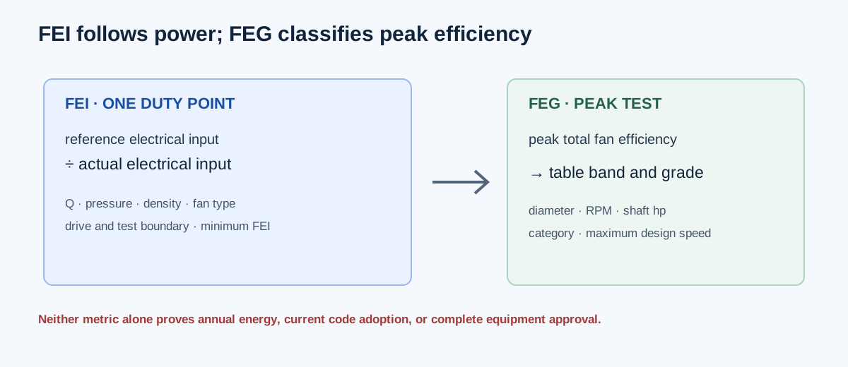
| Question | FEI | FEG |
|---|---|---|
| Primary quantity | Reference electrical input ÷ actual electrical input | Peak total fan efficiency |
| Operating basis | One tested or source-rated duty point | Verified peak efficiency and test/design speed scope |
| Pressure basis | Static or total according to fan type/configuration | Total fan efficiency |
| Drive treatment | Actual electrical input or specified bare-shaft default route | Fan-only peak efficiency; drive losses excluded |
| Output | FEIs or FEIt and power headroom | Table-based FEG grade or explicit out-of-range result |
Choose the method and record the rating boundary
For FEI, identify the exact fan type, AMCA 214-21 test configuration, pressure basis, airflow, density, and actual electrical input at the same duty point. The electrical route requires tested or source-rated electrical input, including the applicable controller boundary where fitted. The bare-shaft route uses the implemented default drive and motor chain only when that scope is appropriate; it is not a substitute for a supplied motor/VFD package.
For FEG, enter actual impeller diameter, verified peak total efficiency, peak shaft power, peak test RPM, maximum design RPM, and category. The implemented scope requires diameter at least 5 in, shaft power at least 1 hp, peak RPM below maximum design speed, and a supported category. Values above the highest tabulated band remain ungraded rather than receiving an invented FEG90.
| Method | Required evidence | Review |
|---|---|---|
| FEI electrical | Single-fan duty point, matching pressure/density, actual electrical kW | Reference chain, power boundary, selected minimum |
| FEI bare shaft | Bare shaft hp and qualifying default drive scope | Default motor/drive assumptions and applicability |
| FEG | Peak total fan-only efficiency, diameter, RPM, power, category | Annex A band, diameter cap, speed and category bounds |
Independent FEI example: reference input versus actual input
Use the documented illustrative single-fan point of 50,000 CFM, 6 in. w.g. static pressure, 0.075 lbm/ft³ density, centrifugal unhoused configuration A, and 59.6 kW actual electrical input. The implemented AMCA 214-21 I-P chain gives reference shaft power 84.498605 hp, transmission efficiency 95.876706%, reference motor output 88.132570 hp after the exact chain, motor efficiency 95.224389%, and reference electrical input 69.016413 kW. The independent calculation yields FEI = 69.016413/59.6 = 1.157993502 and 9.416413 kW headroom at a selected minimum FEI of 1.00.
The source comparison records that an AMCA 208-18 illustrative table rounds FEI to 1.16 but prints a reference input of 69.1 kW. The calculator preserves the 214-21 arithmetic and the mismatch instead of silently altering the inputs. Use the exact edition and power boundary named in the result.
Reference shaft hp = (Q+250)(P+0.4ρ/0.075)/(6343.3η₀)
FEI = reference electrical input / actual electrical input
FEI = 69.016413 / 59.6 = 1.157993502
FEI margin = 1.157993502 − 1.00 = 0.157993502
Maximum input at FEI 1.00 = 69.016413 kW
Power headroom = 69.016413 − 59.6 = 9.416413 kW
| Result | Value |
|---|---|
| Reference shaft power | 84.498605 hp |
| Reference electrical input | 69.016413 kW |
| Actual electrical input | 59.600000 kW |
| FEI | 1.157993502 |
| FEI margin at minimum 1.00 | 0.157993502 |
| Electrical power headroom | 9.416413 kW |
Independent FEG example: classify a peak efficiency band
Use a 500 mm actual impeller diameter (19.68503937 in), verified 79% peak total fan efficiency, 1,800 RPM peak test speed, 2,000 RPM maximum design speed, 1 hp peak shaft power, and category C. The Annex A continuous curve at 500 mm gives an FEG85 upper boundary of 81.470402% and a lower boundary of 76.913019%. Because the assignment uses lower-exclusive and upper-inclusive bounds, 79% falls within FEG85.
The 1 hp and 2,000 RPM values are scope-support inputs in the calculator example; they are not claimed as values printed in the source example. FEG excludes drive losses and depends on the verified peak fan-only efficiency and applicable test method.
d = min(500 mm, 1,016 mm) = 500 mm
FEG85 lower = 76.913019% (exclusive)
FEG85 upper = 81.470402% (inclusive)
76.913019% < 79.000000% ≤ 81.470402% → FEG85
| Input or boundary | Value |
|---|---|
| Actual impeller diameter | 500 mm |
| Peak total efficiency | 79% |
| FEG85 lower boundary | 76.913019%, exclusive |
| FEG85 upper boundary | 81.470402%, inclusive |
| Assigned grade | FEG85 |
Interpret the rating before procurement or compliance use
A positive FEI margin means the entered actual electrical input is below the reference input permitted by the selected minimum. It does not estimate annual energy, account for a schedule, or prove that the fan reaches the duty point in the installed system. Check the fan curve, system curve, controls, density, motor/VFD, accessories, and operating range separately.
An FEG assignment means the entered peak total efficiency falls within the implemented table band for the entered diameter and category. It does not include drive losses and does not establish a complete package rating. Review the source edition, test method, category, maximum speed, power scope, and any table/figure boundary discrepancy before using the grade.
| Result | Establishes | Still requires |
|---|---|---|
| FEI pass | A duty-point power ratio meets the selected criterion | Matching test boundary, operating point, fan/system curve, annual schedule |
| FEI fail | Entered actual power exceeds the selected criterion | Cause analysis and applicable exemption or threshold review |
| FEG grade | Peak total efficiency lies in a supported band | Product test applicability, drive/package review, adopted requirement |
| Out of table | The supplied value is outside supported classification | More applicable source data; no invented grade |
FAQs
Is FEI the same as FEG? No. FEI is a duty-point reference electrical-input ratio; FEG is a table-based peak total-efficiency grade.
Can nameplate motor horsepower serve as actual FEI electrical input? No. The electrical route needs the applicable measured or source-rated electrical input at the same duty point and boundary.
Can FEG be calculated from one ordinary operating point? No. The input must be a verified peak total fan-only efficiency in the applicable scope.
Does a high FEI or FEG automatically prove code compliance? No. The calculator does not select jurisdictional thresholds, exemptions, certification, or current adoption.
Conclusion and limits
Use FEI when the decision concerns a defined duty-point electrical comparison, and FEG when the evidence is a verified peak total-efficiency classification. Record the edition, fan type, pressure basis, drive scope, power boundary, diameter, speed, and category with the result.
The AMCA references support the implemented rating distinctions and pinned examples. They do not authenticate user-entered product data or establish a universal procurement, energy-code, or compliance conclusion for another project.