
Power is a chain of matched boundaries
Air power is the pressure-energy rate delivered to the air. Fan shaft power is higher when fan efficiency is below 100%, and electrical input is higher again when motor and drive losses are included. Each efficiency belongs to a defined pressure and power boundary. Total pressure must use total fan efficiency; static pressure must use static fan efficiency.
The Fan Power Calculator evaluates one operating point. It does not select a motor, estimate starting current, choose a breaker or wire, predict annual energy cost, or convert a TESP reading into fan pressure. Use a pressure value and efficiency that describe the same fan, speed, airflow, density, and pressure definition.
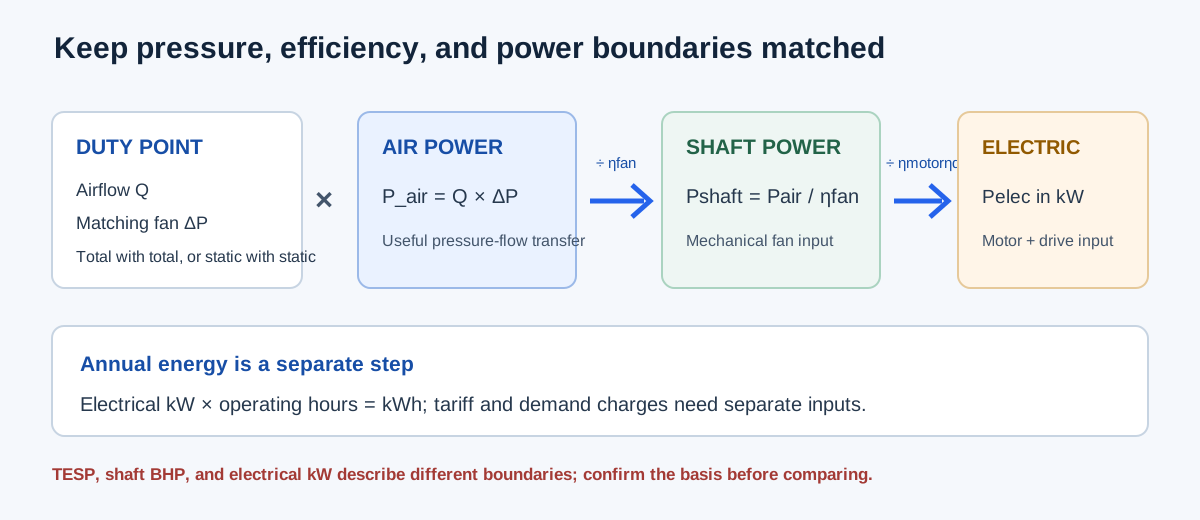
| Stage | Equation | Power boundary |
|---|---|---|
| Air power | Pair airflow with matching pressure | Energy transferred to the air |
| Shaft power | Air power / fan efficiency | Mechanical fan shaft input |
| Electrical input | Shaft power / motor efficiency / drive efficiency | Electrical power drawn at the modeled boundary |
| Annual energy | Electrical kW × hours | Separate schedule and tariff calculation |
Select the pressure and efficiency basis
Choose Fan total pressure and total efficiency when the pressure is a fan total-pressure rise and the fan efficiency is defined on that basis. Choose Fan static pressure and static efficiency when both inputs use the static basis. Enter matching fan pressure rise in inches of water gauge, not an interchangeable TESP or arbitrary component pressure.
Enter efficiencies as percentages in the form. The calculator converts them to fractions internally. A 100% efficiency is an ideal arithmetic boundary accepted by the calculator; a real product will have a lower applicable value. Use efficiency at the intended operating point rather than a maximum nameplate or catalog value from another condition.
P_air = Q × ΔP, with IP-to-SI conversion
P_shaft = P_air / ηfan
P_electric = P_shaft / (ηmotor × ηdrive)
Specific electrical input = P_electric / Q
| Field | Use | Do not substitute |
|---|---|---|
| Operating airflow | CFM at the same duty point | Design airflow from another condition |
| Matching fan pressure rise | Fan total or fan static pressure selected in the form | TESP, filter drop, or total system loss without a boundary conversion |
| Fan efficiency | Total or static efficiency matching pressure | Peak catalog efficiency on another pressure basis |
| Motor/drive efficiency | Electrical loss chain at intended load | Motor nameplate horsepower or assumed zero drive loss |
Enter and review the duty point
Enter the actual airflow in CFM and matching fan pressure rise in inches of water gauge. Select total pressure with total fan efficiency, or static pressure with static fan efficiency; then enter fan, motor, and drive efficiencies as percentages. Outputs update automatically, and efficiencies must be above 0% and no more than 100%.
Check that every value describes the same operating point and air condition. The form has no separate altitude, temperature, or density correction, so use pressure and efficiency already applicable to the stated condition. Zero pressure is accepted and produces zero power; airflow must remain positive for the specific-input result.
| Step | Form entry | Check |
|---|---|---|
| 1 | Operating airflow, CFM | Use flow at the fan duty point |
| 2 | Total-pressure or static-pressure mode | Match the pressure definition |
| 3 | Fan pressure rise, in. w.g. | Do not substitute TESP without a pressure-plane conversion |
| 4 | Fan, motor, and drive efficiencies, % | Use values for the same duty and load |
| 5 | Review air W, shaft BHP, electrical kW, W/CFM | Keep each output boundary distinct |
Independent 500 Pa example
Use 1 m³/s of air at 500 Pa, fan efficiency 65%, motor efficiency 92%, and drive efficiency 97%. Convert the flow: 1 m³/s = 2,118.880003 CFM. Convert pressure: 500 Pa = 500/249.08891 = 2.007315 in. w.g. Air power is directly 1 × 500 = 500 W.
Shaft power = 500/0.65 = 769.230769 W, or 1.03156 BHP using 745.699871582 W/BHP. Electrical input = 769.230769/(0.92 × 0.97) = 861.979795 W, or 0.861980 kW. Specific electrical input = 861.979795/2,118.880003 = 0.406809 W/CFM.
The calculator example displays about 500 W air power, 1.032 BHP shaft power, and 0.862 kW electrical input. Do not round the pressure or airflow before calculating the final result; round only the displayed answer.
1 m³/s = 2,118.880003 CFM; 500 Pa = 2.007315 in. w.g.
Pshaft = 500/0.65 = 769.230769 W = 1.03156 BHP
Pelectric = 769.230769/(0.92×0.97) = 861.979795 W = 0.861980 kW
Specific input = 861.979795/2,118.880003 = 0.406809 W/CFM
| Result | Independent value | Calculator display |
|---|---|---|
| Air power | 500 W | 500 W |
| Shaft power | 1.03156 BHP | 1.032 BHP |
| Electrical input | Approximately 0.862 kW | 0.862 kW |
| Specific electrical input | 0.406809 W/CFM | 0.406809 W/CFM |
Interpret the result at the duty point
Air power is the useful pressure-flow product. Shaft power shows the mechanical input needed under the entered fan efficiency. Electrical input includes the entered motor and drive losses. A lower fan efficiency or motor loading changes the chain even when airflow and pressure remain unchanged.
Use electrical input with operating hours and rates in the fan-energy calculator. Use shaft power with fan and motor limits. Use the pressure basis with a compatible fan curve and system curve. If pressure or efficiency is measured at a different plane or definition, resolve that boundary before comparing power results.
| Output | Supports | Requires separate review |
|---|---|---|
| Air power | Pressure-flow energy comparison | Fan performance and pressure definition |
| Shaft BHP | Mechanical fan load comparison | Motor, belt, VFD and speed limits |
| Electrical kW | Operating-energy calculation | Metering, demand charges, protection and duty schedule |
| W/CFM | Duty-point intensity comparison | Equivalent service and operating conditions |
FAQs
Is TESP the fan pressure to enter? Not automatically. TESP is an external equipment pressure boundary; fan total or static pressure is defined at the fan planes. A compatible pressure balance is needed before converting one to the other.
Can shaft BHP be used as electrical kW? No. Divide by applicable motor and drive efficiencies to estimate electrical input, or use measured electrical kW. Can the result predict an annual bill? No. Annual energy also needs operating hours and applicable rates; demand and fixed charges require a separate bill model.
Does the calculator correct for air density or choose a fan? No. Confirm manufacturer performance at the actual air condition and obtain the duty-point efficiency, motor/drive data, and allowable operating range independently.
Conclusion and limits
Match pressure definition, fan efficiency, airflow, motor efficiency, and drive efficiency before interpreting the power chain. The result is a duty-point estimate with visible units; it is not a motor selection or electrical design approval.
ASHRAE fan definitions and the cited AMCA test standard provide the pressure and efficiency context. The calculator does not certify the measurement method or authenticate entered equipment data.