
Free movement is an endpoint estimate
A straight, homogeneous, unrestrained duct run changes length as its wall temperature changes. The calculator estimates that free axial movement relative to the installation state. Positive movement means the run lengthens; negative movement means it shortens.
This is a movement input for a separate support and flexibility review. It does not determine actual constrained displacement, anchor force, guide spacing, expansion-joint travel, buckling, joint capacity, or a material temperature rating.
| Quantity | Meaning |
|---|---|
| Signed endpoint movement | Free change from installation temperature |
| Maximum expansion | Positive movement relative to installation |
| Maximum contraction | Negative movement magnitude relative to installation |
| Full service range | Free movement from minimum to maximum wall temperature |
| Linear strain | Coefficient × temperature difference |
Enter wall temperatures and the applicable coefficient
Enter the unstrained duct reference length in feet at the installation wall temperature, minimum and maximum uniform duct-wall temperatures in °F, and a positive linear expansion coefficient in millionths per °F. Confirm that the coefficient applies to the actual material and the full temperature interval. If a source gives a coefficient per °C, convert it before entry; the calculator does not select a material preset.
The model uses wall temperature, not automatically the airstream or ambient temperature. Insulation, heat transfer, solar exposure, exhaust duty, and gradients may make actual wall temperature different from either air temperature. Use the endpoint outputs to plan a separate restraint and movement review.
| Input | Unit | Check |
|---|---|---|
| Installed reference length | ft | Straight unstrained length at installation |
| Installation wall temperature | °F | Reference state for signed movement |
| Minimum/maximum wall temperature | °F | Uniform states; minimum ≤ maximum |
| Linear coefficient | millionths/°F | Positive and valid across the interval |
Independent 100-foot PVC example
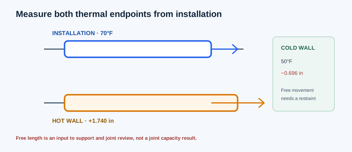
Use a 100 ft installed reference length at 70°F, a 50°F minimum wall temperature, a 120°F maximum wall temperature, and a documented mean coefficient of 29 millionths/°F. The coefficient is α = 29 × 10⁻⁶/°F. At the cold endpoint, ΔT = 50−70 = −20°F, so movement is 1,200 × 29×10⁻⁶ × (−20) = −0.696 in. At the hot endpoint, ΔT = 120−70 = 50°F, so movement is 1,200 × 29×10⁻⁶ × 50 = +1.740 in.
The full service movement from 50°F to 120°F is 1,200 × 29×10⁻⁶ × 70 = 2.436 in. Free endpoint lengths are 99.942 ft and 100.145 ft. The calculator displays 1.74 in expansion, 0.696 in contraction, and 2.436 in full service range.
α = 29 × 10⁻⁶/°F
ΔL_min = 12×100×α×(50−70) = −0.696 in
ΔL_max = 12×100×α×(120−70) = +1.740 in
Service range = 12×100×α×(120−50) = 2.436 in
L_min = 100(1−0.00058) = 99.942 ft
L_max = 100(1+0.00145) = 100.145 ft
| Result | Independent value | Calculator display |
|---|---|---|
| Cold endpoint movement | −0.696 in | −0.696 in |
| Hot endpoint movement | +1.740 in | +1.740 in |
| Maximum contraction | 0.696 in | 0.696 in |
| Maximum expansion | 1.740 in | 1.740 in |
| Full service range | 2.436 in | 2.436 in |
| Free endpoint lengths | 99.942 ft and 100.145 ft | 99.942 ft and 100.145 ft |
Read movement from the installation state
Maximum expansion and contraction are measured from the installation temperature. If both operating temperatures are hotter than installation, contraction from installation is zero even though the operating range still has a nonzero cycle. If both are colder, expansion from installation is zero. The full service range always follows the difference between the two stated operating wall temperatures.
The result is sensitive to length, coefficient units, and wall-temperature assumptions. A coefficient copied from a different material or temperature interval can make the movement estimate look precise while describing the wrong duct.
| Condition | Expansion/contraction output | Service range |
|---|---|---|
| Installation inside operating range | Both may be nonzero | Often less than their sum if endpoints are asymmetric |
| Installation below both states | Expansion positive; contraction zero | Difference between operating states |
| Installation above both states | Contraction positive; expansion zero | Difference between operating states |
| Equal operating endpoints | One signed displacement from installation | Zero cycling range |
Use the movement in the support and joint review
Carry the signed endpoint movements and full service range into the project’s guide, anchor, support, flexible-connection, equipment-nozzle, and expansion-joint review. Check temperature gradients, branch restraints, fittings, insulation, penetrations, hangers, friction, and whether the run can actually move in the assumed direction.
Do not turn the free movement into a joint capacity or anchor force without a restraint model. A constrained run can develop forces and stresses that the free-length calculation intentionally does not model.
| Question | Evidence needed |
|---|---|
| Can the endpoint move? | Guide/anchor layout and support friction |
| Where is movement absorbed? | Flexible connection, joint, loop, offset, or equipment allowance |
| What temperature reaches the wall? | Thermal model or measured wall temperature |
| Does the material remain suitable? | Product temperature and coefficient documentation |
| Are gradients important? | Segmented temperature and restraint analysis |
FAQs
Can I use airstream temperature as wall temperature? Only when the project evidence supports that assumption. The calculator requires a wall-temperature basis and does not derive it from airflow.
Does the result select an expansion joint? No. Joint travel, pressure class, alignment, material, installation, and restraint require product and project data.
Is the service range the expansion plus contraction from installation? Only when installation lies between the two operating states. The range is always based on maximum minus minimum wall temperature.
Does the formula apply to a restrained or nonuniform run? It is a free linear estimate for one straight run with one positive constant or applicable mean coefficient. Restraint and gradients need another model.
Conclusion and limits
Use the installed length, wall-temperature endpoints, and a documented coefficient to calculate signed free movement. Then use those values as inputs to the actual guide, anchor, support, flexible-connection, and equipment interface review.
The cited thermal-expansion relation and duct-specific reference support the free-movement arithmetic. They do not establish a material rating, support design, joint capacity, stress, or code approval for a particular installation.