
A critical path is a complete route
A pressure budget compares complete routes between defined equipment and terminal boundaries at stated flows. A critical path is a route whose endpoint pressure requirement and accumulated compatible losses govern the required fan total-pressure rise. The largest isolated component loss is not necessarily the governing route.
Shared trunks are counted once on each route that traverses them; separate parallel branches are not added together as if air passes through every branch in series. A single-fan network also includes both supply/discharge and return/intake sides, with their endpoint total-pressure boundaries on a common datum.
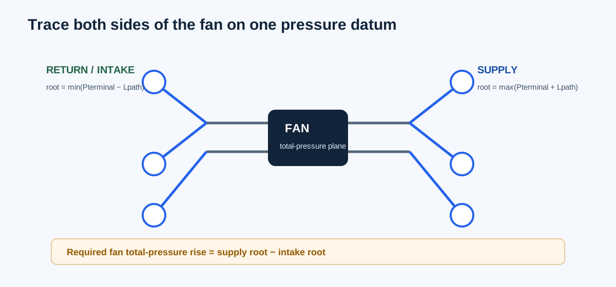
| Side | Path calculation | Root result |
|---|---|---|
| Supply/discharge | Endpoint total pressure + losses along its complete route | Maximum endpoint bound |
| Return/intake | Endpoint total pressure − losses along its complete route | Minimum endpoint ceiling |
| Fan requirement | Supply root − intake root | Required fan total-pressure rise |
Choose the implemented path-check mode
The path-pressure calculator has distinct modes: sum one entered series path; compare two supplied complete path totals; trace a complete scheduled-flow supply and return/intake tree for one fan; or solve its constrained fixed-quadratic tree. This guide’s worked example uses the scheduled-flow network mode. Do not treat the simple two-total comparison as the full network calculation.
For the schedule mode, first confirm a single-fan basis and common airflow and total-pressure references. Enter one row per actual segment with unique ID, side, parent, child, CFM, and nonnegative total-pressure loss. Parent 0 is the fan pressure plane on each side. Enter one terminal boundary for every leaf, including design flow and signed total pressure on the common datum. An optional fan point must be fan total pressure at the same complete flow and density basis.
Every internal node must balance: incoming segment flow equals the sum of its downstream sections. The intake tree is numbered outward from the fan for bookkeeping even though physical return air travels toward the fan. The tool checks complete connectivity, flow continuity, each endpoint, and every complete route.
| Step | Enter or confirm | Check |
|---|---|---|
| 1 | One-fan basis and shared pressure/flow reference | No unstated density or standard-flow conversion |
| 2 | All supply and return/intake segment rows | Correct side, IDs, parent/child and actual loss |
| 3 | Every leaf terminal flow and boundary total pressure | No omitted or duplicated terminal |
| 4 | Optional fan total-pressure point | Same full scheduled flow and basis |
| 5 | Review root bounds and per-terminal paths | Check the governing routes and additional-loss allowances |
Independent complete-network example
Use the constructed example at 1,200 CFM through one fan. Supply terminal 5 has a 0.10 in. w.g. endpoint total-pressure requirement and losses of 0.08 + 0.03 + 0.11 = 0.22 in. w.g., giving a supply root bound of 0.32 in. w.g. Other supply endpoint bounds are 0.23 and 0.20 in. w.g.; terminal 5 governs.
Return/intake terminal 2 has boundary total pressure −0.02 in. w.g. and route losses 0.06 + 0.09 = 0.15 in. w.g., giving an intake root ceiling of −0.17 in. w.g. Terminal 1 gives −0.13 in. w.g., so terminal 2 governs. Required fan total-pressure rise is 0.32 − (−0.17) = 0.49 in. w.g. A constructed matching fan point of 0.55 in. w.g. therefore leaves 0.06 in. w.g. arithmetic margin.
All values are teaching data, not product or field ratings. They show how signed endpoint total pressures, shared trunks, and both fan sides enter the arithmetic. Replace the complete schedule with project evidence before using it for a duty decision.
Supply root = max(Pterminal,total + Lpath)
Intake root = min(Pterminal,total − Lpath)
Required fan total-pressure rise = supply root − intake root
Example: 0.32 − (−0.17) = 0.49 in. w.g.
| Quantity | Independent value | Calculator value |
|---|---|---|
| Supply terminal 5 path loss | 0.08 + 0.03 + 0.11 = 0.22 in. w.g. | 0.22 in. w.g. |
| Supply root bound | 0.10 + 0.22 = 0.32 in. w.g. | 0.32 in. w.g. |
| Intake terminal 2 path loss | 0.06 + 0.09 = 0.15 in. w.g. | 0.15 in. w.g. |
| Intake root ceiling | −0.02 − 0.15 = −0.17 in. w.g. | −0.17 in. w.g. |
| Required fan rise / margin | 0.49 / 0.06 in. w.g. | 0.49 / 0.06 in. w.g. |
Keep loss bases and model limits visible
A scheduled segment loss is total-pressure loss at the stated design airflow. Keep the pressure convention consistent across segments, terminals, and the common reference. Fan static pressure, TESP, endpoint static pressure, and total-pressure boundary are not substitutes. Include endpoint velocity or static requirements once in the stated total-pressure boundary, not again as an unnamed component.
The fixed-quadratic tree mode is a separate pressure-driven model. It requires positive passive quadratic resistances, complete topology, compatible pressure nodes, a common zero-total-pressure leaf datum, and documented flow validity intervals. It does not solve general fan/network behavior, junction coefficients, leakage, multiple fans, loops, or active controls.
| The model can show | It cannot establish by itself |
|---|---|
| Governing supplied route and required pressure at stated flows | Actual pressure-driven flow or balanced damper positions |
| Arithmetic margin to a matching fan total-pressure point | Fan curve intersection, stability, or operating range |
| Additional loss allowance by terminal path | A damper setting, authority, sound, or commissioning result |
| Completeness of the rows entered | Authenticity of product data or omitted project components |
FAQs
Should all branch losses be added together? No. Follow each complete route and count its shared segments once. A terminal path does not traverse unrelated parallel branches.
Can an available-pressure margin be split automatically between supply and return? No. The budget reports arithmetic bounds; fan control and pressure allocation require another analysis.
Does this calculation identify a field failure? No. It helps locate a controlling modeled route. Confirm measurements, product data, installed conditions, and omitted paths before assigning a cause.
Conclusion and limits
Trace complete paths on both sides of one fan, use a common total-pressure reference, preserve each shared segment once, and compare only a fan total-pressure point at the same scheduled airflow. Read additional path losses as allowances, not control settings.
The implemented equations follow the stated schedule model and cited system topology. Constructed numbers do not validate equipment, fitting coefficients, field operation, or current code compliance.