
From calculated area to a duct that can fit
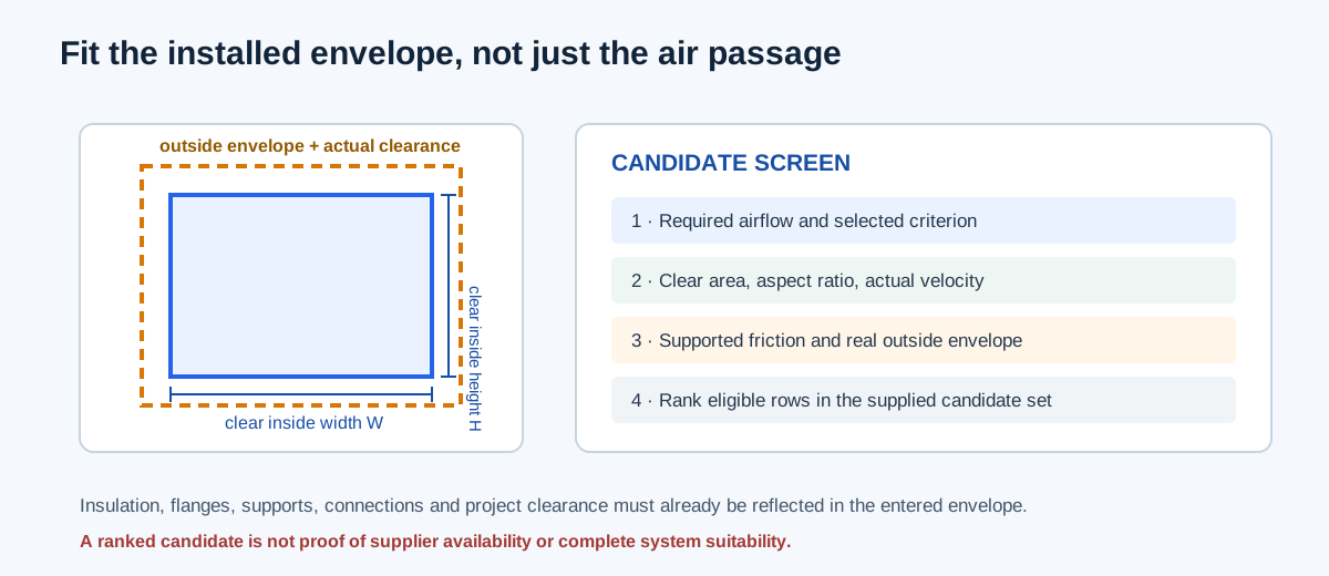
A required clear area does not define one rectangular width and height. A selected aspect ratio or fixed short side determines a family of shapes, while the actual installation envelope must account for insulation, flanges, supports, connections, and project clearance. Clear dimensions describe the air passage; outside dimensions describe the space the installed assembly occupies.
The site’s supplied-size method compares a finite user-entered schedule against explicit criteria and returns the smallest eligible clear area, then the lowest ID on a tie. This ranking is limited to that list. It is not a supplier catalog search, fabrication-size rounding rule, cost optimum, or whole-system design solution.
| Quantity | What to enter or calculate | Common boundary error |
|---|---|---|
| Clear width and height | Inside air-passage dimensions | Using sheet or insulation dimensions as flow area |
| Aspect ratio | Largest clear side ÷ smallest clear side | Treating a project maximum as universal code |
| Outside envelope | Actual installed width and height | Omitting insulation, flanges, supports, or clearance |
| Candidate list | Actual supplied alternatives with unique IDs | Assuming a teaching list represents local inventory |
Enter a theoretical shape or compare supplied candidates
For the fixed-short-side mode, enter design airflow in CFM, selected velocity in FPM, the fixed inside short side in inches, and the maximum width-to-height ratio. The calculation determines the area from airflow and velocity and then solves the long side. Treat the velocity and aspect maximum as project inputs, not defaults established by the calculator.
For available-size selection, provide each candidate’s ID, shape, clear dimensions, and actual outside envelope. Select the required velocity, equivalent-round friction, or combined criterion as appropriate; enter density, kinematic viscosity, and absolute roughness only when friction applies. Enter maximum installation width/height, aspect limit, and rotation permission from the real project. A zero constraint explicitly disables that constraint. Rotation is only appropriate when the actual connection and support arrangement allows it.
Review every eligibility margin and the selected candidate. The routine does not verify stock, current product dimensions, fabrication tolerances, access, structure, sound, fittings, or complete route pressure. Replace constructed example rows with verified project candidates before using the ranking.
| Step | Action | Review |
|---|---|---|
| 1 | Establish airflow and the sizing criterion | State whether velocity, friction, or both govern |
| 2 | Enter clear candidate dimensions and actual envelopes | Keep inside area separate from outside fit |
| 3 | Set project aspect, space, and rotation constraints | Use actual constraints; zero disables a limit |
| 4 | Review each candidate’s margins and support status | Unsupported friction is not a pass |
| 5 | Confirm the selected size against the installation | Check connections, transitions, insulation, and path pressure |
Independent fixed-short-side example
For 400 CFM at a selected 700 FPM, required area is 400/700 = 0.5714286 ft², or 82.2857 in². If the clear short side is fixed at 8 in, the required long side is 82.2857/8 = 10.2857 in. The resulting clear aspect ratio is 10.2857/8 = 1.2857:1, within an explicitly selected 4:1 maximum. The section returns 700 FPM before rounding.
This checks clear geometry only. It does not prove that a 10.2857 × 8 in nominal or fabricated duct exists or fits. If the installation envelope is not supplied, the physical-fit result cannot be determined; add the real insulation, supports, connections, and clearance dimensions before selecting a candidate.
Required area (in²) = Q(CFM)/V(FPM) × 144
Long side = required area / fixed short side
Aspect ratio = long side / short side
| Check | Calculation | Result |
|---|---|---|
| Clear area | 400/700 × 144 | 82.2857 in² |
| Long clear side | 82.2857/8 | 10.2857 in |
| Aspect ratio | 10.2857/8 | 1.2857:1 |
| Average velocity | 400/(82.2857/144) | 700 FPM |
Interpret the candidate ranking narrowly
A candidate may fit the clear-area or velocity criterion and still fail friction, installation space, aspect ratio, or supplied rotation restrictions. Conversely, a friction-only candidate can exceed a separately selected velocity limit. Keep the criteria visible rather than collapsing them into a single unstated judgment.
When an available-size result is selected, read “smallest” as the smallest eligible clear cross-section in the entered candidate set under the chosen limits. Confirm its actual outside envelope and measure the path; then include transitions, elbows, terminal pressure, and other losses in a compatible pressure budget.
| Result state | Meaning | Next action |
|---|---|---|
| Eligible | Supplied dimensions meet the selected numeric constraints | Verify actual product and installed envelope |
| Geometry only | Dimensions are known but friction support or criterion is absent | Do not infer a friction pass |
| No eligible candidate | No entered row satisfies all selected limits | Review criteria and obtain additional actual candidates |
| Selected candidate | Lowest eligible clear area, then lowest supplied ID | Confirm system path and fabrication/stock basis |
FAQs
Is 4:1 a universal maximum aspect ratio? No. It is only a selected input when the project calls for it. The calculator supplies no universal limit.
Does an outside envelope come from the inside size automatically? No. Provide the actual envelope that already accounts for insulation, flanges, supports, and required clearance.
Does the ranking prove the selected size is available? No. The tool ranks the supplied list and does not query an inventory or manufacturer schedule.
Conclusion and limits
Use calculated area and a chosen aspect ratio to generate theoretical geometry, then screen actual candidates against project velocity, friction, and installation constraints. Preserve clear and outside dimensions as separate inputs and describe the candidate list’s source.
The calculator’s ranking rule and geometry are defined by its current implementation. Actual stock, envelope, clearance, fabrication, pressure, noise, and project acceptance criteria must be supplied independently.