
A closed door changes the return path
A room supplied by an air handler with a central hall return needs a path for air to leave when its door is closed. The required outward transfer depends on room supply and other known inflows, less ducted return, exhaust, and other known outflows. A grille opening alone does not establish how much air the full connection can pass at a specified room-to-hall pressure.
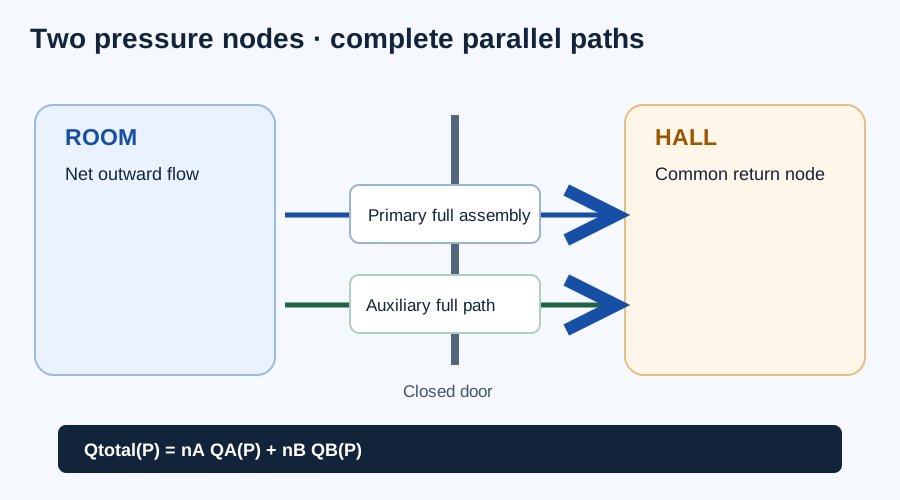
The Return Air Pathway Calculator evaluates one or two types of complete paths connected in parallel between the same room and hall. Each path needs its own pressure-flow curve for the actual assembly and air basis. Two grilles joined by a sleeve form one complete path, not two parallel paths.
| Information | What it describes | What remains unknown |
|---|---|---|
| Grille free area | Open area of one component | Complete path resistance and capacity |
| Complete path curve | Flow versus pressure for the assembled route | Field changes outside its tested/source conditions |
| Selected pressure limit | Project comparison criterion | Whether the installed room meets it |
| Measured closed-door pressure | Installed room-to-hall condition | Its relationship to a different operating setting |
Enter the net flow, path curves, and selected limits
Enter a positive Net room-to-hall transfer requirement in CFM on the common actual-flow basis and a positive selected pressure limit in pascals. Document how the net transfer was obtained. Do not infer supply from register size or credit uncontrolled exterior leakage as a known return path.
Enter the Existing identical primary paths count and a pressure/flow curve for one complete primary path. Each curve requires 2–100 rows with pressure and flow both strictly increasing. A source-justified (0,0) row is allowed, but the tool never adds an origin automatically. Record the assembly, flow direction, tap locations, door condition, air basis, source, and revision.
If retaining another path type, provide its separately characterized complete curve, source, and fixed count. This could represent a measured door gap or another installed assembly, but geometry alone does not provide a curve. Comparison mode adds a second selected pressure limit and uses the same airflow, path curves, and existing counts for both scenarios.
- Existing primary and retained auxiliary counts are whole numbers from 1 to 10,000 when active.
- The selected limit must lie inside every active curve’s supplied pressure range.
- All curves must share a compatible airflow/air-condition basis and connect the same pressure nodes in the modeled direction.
- Complete paths in series must be represented by an already combined assembly curve, not entered as parallel path types.
Add parallel capacities at the same pressure
At a given pressure P, the calculator reads or linearly interpolates each path’s flow within its supplied range. It multiplies by each type’s quantity and sums flows. The minimum primary count supplies the remaining requirement after the retained auxiliary capacity is credited. It rounds up to a whole path and reports additions separately from the minimum total.
Pressure prediction reverses the combined piecewise-linear curve. It is reported only where the requested flow lies within the active curves’ shared support. A supported capacity at the selected pressure limit can exist even when a current or minimum-count pressure prediction is unavailable. An omitted pressure is not zero pressure.
Qtotal(P) = nA QA(P) + nB QB(P)
nA,min = max[0, ceil((Qrequired − nB QB(Plimit))/QA(Plimit))]
Additional primary paths = max(0, nA,min − nA,existing)
Between source points: Q(P) = Q₁ + [(P − P₁)/(P₂ − P₁)](Q₂ − Q₁)
| Symbol | Meaning | Unit |
|---|---|---|
| P | Common room-to-hall pressure difference | Pa |
| QA(P), QB(P) | One complete path’s flow at that pressure | CFM on the common basis |
| nA, nB | Number of identical parallel paths of each type | whole paths |
| Qrequired | Net outward room transfer | CFM |
| Plimit | Selected project pressure limit | Pa |
Independent example: one existing path and a 3 Pa limit
Use constructed primary-path points of (1 Pa, 50 CFM), (2, 80), (3, 100), (5, 140), and (8, 180). The room needs 120 CFM outward transfer, has one existing primary path, and has no credited auxiliary path. Select 3 Pa as the example limit; it is not asserted as a universal requirement.
At 3 Pa, one path carries 100 CFM, so its current capacity margin is 100 − 120 = −20 CFM. The minimum total is ceil(120/100) = 2 paths, or one additional path. With the existing single path, 120 CFM lies midway between 100 CFM at 3 Pa and 140 CFM at 5 Pa: pressure = 3 + (120 − 100)/(140 − 100) × (5 − 3) = 4 Pa.
With two paths, capacity is 100 CFM at 1 Pa and 160 CFM at 2 Pa. Solving for 120 CFM gives 1 + (120 − 100)/(160 − 100) = 1.333333 Pa. The calculator reports two total primary paths, one additional path, 4 Pa current pressure, and 1.333 Pa for the minimum-count arrangement. Calculations use unrounded interpolation; the displayed pressure rounds to three decimals.
| Pressure | One path capacity | Two parallel paths |
|---|---|---|
| 1 Pa | 50 CFM | 100 CFM |
| 2 Pa | 80 CFM | 160 CFM |
| 3 Pa | 100 CFM | 200 CFM |
| 5 Pa | 140 CFM | 280 CFM |
| 8 Pa | 180 CFM | 360 CFM |
Compare limits without inventing unsupported pressure results
Using the same constructed curve and 120 CFM requirement, a 1 Pa limit has 50 CFM capacity per path, so it requires ceil(120/50) = 3 total paths. At 3 Pa, it requires 2. Comparison mode reports one fewer total primary path in the 3 Pa scenario. This is sensitivity to the two entered criteria; the calculator does not choose which criterion applies.
The three-path arrangement would need 40 CFM per path to pass 120 CFM. That is below the curve’s first supplied flow of 50 CFM at 1 Pa. Its operating pressure is therefore outside support and must remain unreported. Do not extend the first line to an assumed origin to manufacture a pressure below 1 Pa.
| Selected limit | Capacity per path | Minimum total / additions | Minimum-count pressure |
|---|---|---|---|
| 1 Pa | 50 CFM | 3 total / 2 additional | Outside supplied support; withheld |
| 3 Pa | 100 CFM | 2 total / 1 additional | 1.333 Pa |
Verify the complete installed route
A nonnegative modeled capacity margin applies only to the supplied assembly curves and assumed room flow. Check that the actual grilles, sleeves, baffles, duct routing, door gap, finished floor, pressure taps, and flow direction match the source. Curves for unlike products, corrected versus actual airflow, or different installation conditions should not be blended.
Verify delivered room flow and room-to-hall pressure with doors closed at the relevant air-handler operating state after installation. A minimum total smaller than the installed count is not an instruction to remove working paths. Fire/smoke separation, acoustic privacy, product fit, and other project requirements need separate review. The useful outcome is a documented comparison and an installed check, not a universal door-undercut or grille-size rule.
FAQs
Does the required transfer airflow determine a grille size by itself? No. The path curve, pressure criterion, count, and installed geometry are also required.
Can capacities from different pressures be added? No. Add parallel capacities only at the same stated pressure.
Does the result predict room pressure? No. It compares the entered path capacity with the entered airflow requirement.
Conclusion and limits
Calculate the net transfer requirement, evaluate complete path curves at the selected pressure, and carry the required path count into the installed return-route review.
The result does not predict room pressure or approve a grille, door gap, or transfer assembly without matching product and installation data.