
Separate the airflow target from delivered exhaust
The Bathroom Exhaust Fan CFM Calculator applies the HVI area or fixture guideline to estimate an initial intermittent exhaust target. That target helps define the duty you need to investigate. Actual exhaust depends on the fan and the resistance of its installed duct, fittings, damper, and termination.
A fan’s nominal airflow does not establish its delivered airflow at another resistance. Select and evaluate the fan using product performance at a matching pressure basis, then verify installed flow. Local requirements, room arrangement, controls, noise, and the replacement-air path remain part of that decision.
| Stage | Question | Evidence needed |
|---|---|---|
| Guideline calculation | What initial intermittent CFM should be investigated? | Measured floor area or applicable fixture counts |
| Fan/duct review | Can the product provide that flow through this route? | Complete route loss and matching fan performance |
| Installed verification | What flow is actually exhausted? | An appropriate field airflow measurement |
Choose the applicable area or fixture mode
Measure the bathroom floor area in square feet and select the matching HVI guideline method. For a room smaller than 100 ft², the calculator uses 1 CFM/ft² with a 50 CFM minimum. For a room larger than 100 ft², it adds 50 CFM per toilet, shower, or ordinary bathtub and 100 CFM per jetted tub.
The reviewed guideline distinguishes smaller and larger than 100 ft² without resolving exactly 100 ft². The calculator therefore withholds a result at that boundary; obtain the applicable project interpretation. Do not silently use either mode there. These are intermittent-exhaust guidelines, not a determination of locally adopted code.
Area mode, A < 100 ft²: Qguideline = max(50, A × 1 CFM/ft²)
Fixture mode, A > 100 ft²: Qguideline = 50(Ntoilet + Nshower + Ntub) + 100 Njetted
- Enter Bathroom floor area in either mode; the area validates which method applies.
- In larger-room mode, enter whole nonnegative counts for Toilets, Showers, Ordinary bathtubs, and Jetted tubs, with at least one fixture.
- Count a jetted tub only in its own field. Do not count the same fixture again as an ordinary bathtub.
- Review an enclosed toilet compartment’s exhaust provision separately; a room total does not establish air removal at every location.
Independent examples for both modes
Area example: an 8 × 10 ft bathroom has A = 80 ft². The area rate gives 80 CFM, which exceeds the 50 CFM floor. The result is max(50, 80) = 80 CFM, matching the calculator’s area example. A constructed 6 × 6 ft room would have A = 36 ft² and return max(50, 36) = 50 CFM.
Fixture example: use a constructed 150 ft² bathroom with one toilet and one shower, no ordinary tub, and no jetted tub. The total is 50 × (1 + 1 + 0) + 100 × 0 = 100 CFM, matching the larger-room example. Adding one jetted tub would add 100 CFM in this arithmetic. Fixture arrangement and the applicable requirements still govern the exhaust design.
| Case | Inputs | Calculation | Result |
|---|---|---|---|
| Area example | 80 ft² | max(50, 80) | 80 CFM |
| Small-room floor | 36 ft² | max(50, 36) | 50 CFM |
| Fixture example | 150 ft²; one toilet, one shower | 50 × (1 + 1) | 100 CFM |
| Unresolved boundary | Exactly 100 ft² | No method chosen by the calculator | Project interpretation required |
Check the complete duct route at the target flow
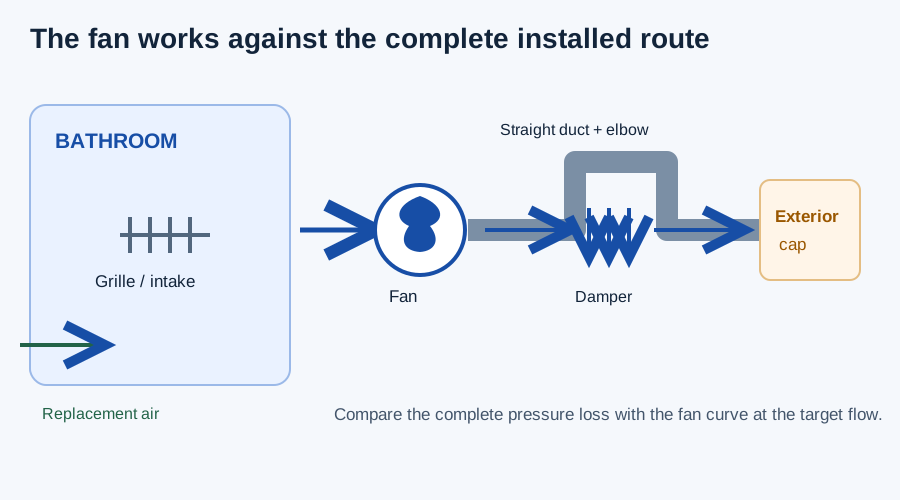
Draw the installed route from the room inlet to the exterior. Record duct shape, clear inside size, length, fittings, flex condition if present, backdraft damper, and termination. Obtain applicable component losses and the actual fan curve or rated performance. Use one operating flow and compatible pressure definitions for the comparison.
The Duct Pressure Drop Calculator can estimate a modeled duct section’s loss from geometry, airflow, air properties, roughness, and supplied fitting coefficients. It does not supply product losses for a bathroom damper or wall cap. Add such losses only from matching data, once each, and compare the complete path with the fan performance. Avoid combining a fitting equivalent-length allowance and its separate pressure drop for the same fitting.
A larger duct or a simpler route can change resistance, but its airflow effect must be checked against the actual fan/system relationship. The guideline calculator cannot infer the new operating point from a change in duct size.
| Part | Record | Reason |
|---|---|---|
| Straight duct | Inside size, length, material, flow and air properties | Establishes the section friction basis |
| Bends and transitions | Actual geometry and matching loss method | Nominal fitting names do not establish resistance |
| Flex duct, if used | Installed length, compression, sag and bend condition | Installed resistance may differ from the stretched reference |
| Damper and termination | Exact product and loss data at the comparison flow | These components can consume part of the pressure budget |
| Fan | Applicable curve, pressure definition and operating setting | Matches the equipment to the full route |
Verify airflow and the room’s incoming path
After installation or a change, verify exhaust flow at the intended fan setting with the relevant door, damper, and control conditions. Record the method and operating state. The calculation itself neither measures the exhaust nor establishes a measurement tolerance.
Check where replacement air enters. An exhaust target does not size a transfer opening, establish building pressure, or address interactions with combustion appliances. Use a separate flow balance or pressure investigation where those questions apply. Do not infer safety from equal supply/exhaust CFM or from a passing duct calculation.
Use the guideline as the beginning of the selection
Use area or fixture mode to calculate the initial intermittent target, respecting the unresolved 100 ft² boundary. Then connect that target to the actual duct route, fan data, replacement-air path, controls, and a delivered-flow check. Keep the guideline result and the field result labeled separately.
The sources below provide guideline and installation context. They do not replace the adopted requirements or the performance data for the exact fan and accessories being installed.
FAQs
Does the guideline CFM prove delivered exhaust? No. Fan performance and the complete installed route determine delivered flow.
Can I count a jetted tub as an ordinary tub too? No. Enter it in the jetted-tub field for the selected fixture method.
Does the calculator select a replacement-air path? No. Check transfer, makeup, door, and building-pressure conditions separately.
Conclusion and limits
Use the guideline calculation to set an investigation target, then check the complete installed route and verify delivered exhaust under the intended condition.
The guideline and route screen do not certify capture, pressure balance, fan selection, or code compliance.