
What the sizing calculator decides
The Duct Size Calculator has separate modes for target velocity, rectangular aspect ratio, a fixed short side, circular-reference friction, flat-oval friction, and a supplied candidate schedule. All of them begin with a design airflow, but they do not solve the same constraint.
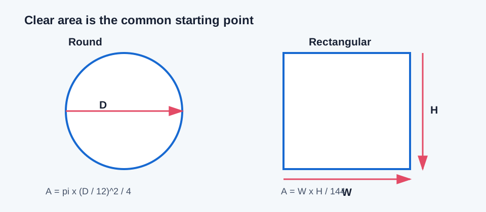
Round and rectangular ducts can carry the same CFM while having different clear areas, perimeters, hydraulic behavior, installation envelopes, and fitting choices. A geometric conversion preserves a defined relationship; it does not automatically prove equal pressure loss in an installed route.
| Mode | Required inputs | Primary result | What to check next |
|---|---|---|---|
| Round or rectangular velocity | Design CFM, target FPM, and shape inputs | Theoretical clear dimensions | Actual velocity, nominal size, route pressure |
| Rectangular fixed short side | Design CFM, target FPM, short side, maximum aspect ratio | Long side and resulting ratio | Clearance, outside envelope, transition geometry |
| Round or rectangular friction | Design CFM, friction rate, density, viscosity, roughness | Theoretical size on a circular-reference basis | Turbulence condition, actual-section velocity, fittings |
| Available-size selection | Entered candidates, envelopes, project velocity/friction criteria | Smallest eligible candidate in the supplied list | Actual product/fabrication data and installation fit |
Choose the method and enter the fields
Start with design airflow for the section being sized. For velocity modes, enter the selected target velocity; this is an explicit design input, not a universal code limit. For rectangular modes, enter width-to-height ratio or the fixed short side. For friction modes, enter the air density, kinematic viscosity, absolute roughness, and selected straight-duct friction rate together.
- Use clear inside dimensions for the air passage. In an installation-envelope mode, keep the supplied outside width and height separate because insulation, flanges, supports, and project clearance consume space beyond the clear flow opening.
- Use the actual section area when reviewing velocity. Rectangular and flat-oval friction modes use an equivalent-round reference for the straight-duct friction estimate, so their actual-section velocity is a separate output.
- Treat the available-size list as the entered comparison set. The tool does not authenticate a stock schedule, choose a supplier, or round a theoretical result to a product that was not supplied.
Independent velocity-sizing example
For 400 CFM at a selected 700 FPM, required clear area is 400 / 700 = 0.5714 ft². An equal-area round result is D = 12 x sqrt(4 x 0.5714 / pi) = 10.24 in, rounded from 10.2357 in. A 2:1 rectangle has W = sqrt(0.5714 x 2 x 144) = 12.83 in and H = 12.83 / 2 = 6.41 in. The calculator displays approximately 10.2 in and 12.8 x 6.4 in under the same inputs.
Those dimensions are theoretical clear dimensions. If a 12 x 8 in rectangular section is selected instead, its area is 0.6667 ft² and its velocity at 400 CFM is 600 FPM. That candidate is larger than the 700 FPM target area and must be reviewed against the actual project constraints rather than described as the same result.
Velocity sizing: A = Q / V; round D = 12 x sqrt(4A / pi); rectangle W = sqrt(144A x r), H = W / r
| Shape or candidate | Clear area | Independent result | Rounded display |
|---|---|---|---|
| Theoretical round | 0.5714 ft² | D = 10.2357 in | 10.2 in |
| Theoretical rectangle, 2:1 | 0.5714 ft² | W = 12.8285 in; H = 6.4143 in | 12.8 x 6.4 in |
| Example 12 x 8 rectangle | 0.6667 ft² | V = 400 / 0.6667 = 600.0 FPM | 600 FPM |
Independent friction-sizing example
A friction mode needs more than CFM. Using 1,000 CFM, 0.10 in. w.g. per 100 ft, density 0.075 lbm/ft³, kinematic viscosity 0.00016 ft²/s, and roughness 0.0003 ft, an independent Darcy-Weisbach/Colebrook calculation gives a circular reference of about 13.65 in. The corresponding velocity is about 984 FPM, Reynolds number about 116,600, and Darcy friction factor about 0.0189. The calculator example reports 13.646 in, 984.609 FPM, Re about 116,631, and f about 0.01885; the small difference is from the independent friction-factor iteration and rounding.
For a 2:1 rectangular conversion, the calculator then applies its documented equivalent-round relationship. That output is a straight-duct reference result, not a complete pressure prediction for every fitting, transition, liner, or flexible section.
DeltaP/L = f_D x rho x V^2 / (2 x g_c x D); solve the circular reference before shape conversion
| Input or result | Value | Basis |
|---|---|---|
| Design airflow | 1,000 CFM | Same airflow through the circular reference |
| Selected friction rate | 0.10 in. w.g./100 ft | Straight-duct circular-reference target |
| Independent circular reference | 13.65 in | Rounded from 13.6499 in |
| Calculator circular reference | 13.646 in | Existing mode example output |
| Independent velocity | 984 FPM | Rounded from 984.046 FPM |
Compare the result with construction constraints
After the calculator returns a theoretical size, compare clear dimensions with the actual installation envelope. Include insulation, flanges, supports, access, fire or separation requirements, and transition length in the project review. Recalculate the actual velocity after selecting a nominal or supplied size.
A pass in the sizing workbench means that the entered criteria were met for the entered candidate set. It does not rank cost, noise, energy, leakage, fabrication availability, or the whole-system critical path.
- Use the pressure-drop calculator for straight and fitting losses at the chosen airflow.
- Use the shape converter when the decision is explicitly equal area or equal friction; label which basis was selected.
- Use the pressure budget and critical-path tools after the complete route and component losses are documented.
Conclusion and limits
Round sizing is often compact and easy to describe by diameter. Rectangular sizing adds aspect ratio and clearance choices. Friction sizing adds air properties and surface roughness. The correct result is therefore the one that states its constraint, units, and reference basis clearly.
The calculation does not establish a universal velocity limit, a nominal product choice, a flexible-duct correction, fitting loss, fan operating point, or code compliance. Those decisions require their own current project or product evidence.
FAQs
Does a theoretical size equal a stock or fabricated size? No. Confirm the actual candidate schedule and outside installation envelope.
Does equal area mean equal friction? No. The calculator keeps geometric conversion and straight-duct friction equivalence as separate methods.
Does a size pass include fittings, leakage, sound, or fan capacity? No. Those are separate system checks.