
Flexible duct performance belongs to the installed condition
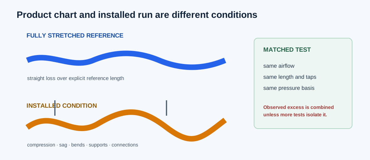
A fully stretched flex-duct chart does not automatically describe a run with longitudinal compression, sag, tight bends, poor support, connection losses, or a different product construction. The product reference and installation condition must be kept together.
The calculator has two methods. Compression mode applies the supported ASHRAE pressure-drop correction to a straight-flex reference after normalizing the reference pressure to the installed axial length. Measured mode compares equal-length, same-airflow reference and installed pressure tests without assigning the excess to one cause.
| Method | Use | Important boundary |
|---|---|---|
| Compression correction | Estimate straight-flex pressure at known longitudinal compression | Reference pressure is straight friction; reference length is explicit |
| Measured comparison | Compare an installed assembly with a matching reference test | Same airflow, length, air basis, taps, and pressure definition |
| Product sizing | Choose diameter from a product chart and duty point | Requires actual product chart and installation condition |
Enter product and installation evidence before calculating
For compression mode, enter airflow, fully extended reference pressure, its pressure-reference length, nominal diameter, fully stretched length of the installed specimen, installed axial length, and pressure budget. The correlation is limited here to 150–400 mm (about 6–16 in.) diameter and 0–45% longitudinal compression.
For measured mode, enter the same airflow, equal-length reference pressure, measured installed pressure, and pressure budget. Match air properties, pressure taps, static/total definitions, product, support, and test condition. Do not apply straight-run length normalization to a complete measured assembly.
| Input | Compression mode | Measured mode |
|---|---|---|
| Airflow | Same comparison duty point | Same comparison duty point |
| Reference pressure | Fully stretched straight loss | Measured equal-length reference |
| Length | Pressure-reference, fully stretched, installed | Equal tested axial length |
| Installation effect | Compression correlation | Observed total difference |
| Budget | Budget minus corrected loss | Budget minus installed measured loss |
Independent compression example from the named equation
Use 470 L/s converted to 995.873602 CFM, a 250 mm diameter converted to 9.842520 in, installed axial length 1.8 m (5.905512 ft), fully stretched specimen length 1.8/0.85 = 2.117647 m (6.947661 ft), and a fully stretched reference loss of 11.4 Pa over the same 1.8 m pressure-reference length. Compression is 100(1−5.905512/6.947661) = 15%.
The pressure-drop correction factor is PDCF = 1 + 0.58×15×exp(−0.00496×250) = 3.517642696. Because the pressure-reference and installed lengths are equal, the normalized fully extended run loss remains 11.4 Pa = 0.045766791 in. w.g. Corrected pressure is 0.160991217 in. w.g.; against a 0.20 in. w.g. budget, margin is 0.039008783 in. w.g.
Kc = 100(1−L_installed/L_FE) = 15%
PDCF = 1 + 0.58Kc exp(−0.00496D_mm) = 3.517642696
Δp_FE,run = 0.045766791 × (5.905512/5.905512) = 0.045766791 in. w.g.
Δp_installed = 3.517642696 × 0.045766791 = 0.160991217 in. w.g.
Budget margin = 0.200000000−0.160991217 = 0.039008783 in. w.g.
| Result | Independent value | Calculator display |
|---|---|---|
| Compression ratio | 15% | 15% |
| Correction factor | 3.517642696 | 3.517642696 |
| Corrected pressure drop | 0.160991217 in. w.g. | 0.160991217 in. w.g. |
| Pressure budget margin | 0.039008783 in. w.g. | 0.039008783 in. w.g. |
Independent measured comparison example
Use a constructed equal-length comparison at 470 CFM: fully extended/reference pressure 0.0458 in. w.g., installed pressure 0.160 in. w.g., and budget 0.20 in. w.g. The measured pressure ratio is 0.160/0.0458 = 3.493449.
The measured increase is 100(3.493449−1) = 249.345% and pressure excess is 0.160−0.0458 = 0.1142 in. w.g. The budget margin is 0.20−0.160 = 0.040 in. w.g. This comparison does not say whether compression, sag, bends, support, connections, or measurement uncertainty caused the excess.
Pressure ratio = 0.160/0.0458 = 3.493449
Increase = (3.493449−1)×100 = 249.345%
Pressure excess = 0.160−0.0458 = 0.1142 in. w.g.
Budget margin = 0.200−0.160 = 0.040 in. w.g.
| Result | Independent value | Calculator display |
|---|---|---|
| Measured pressure ratio | 3.493449× | 3.493449× |
| Measured pressure increase | 249.345% | 249.345% |
| Measured pressure excess | 0.1142 in. w.g. | 0.1142 in. w.g. |
| Pressure budget margin | 0.040 in. w.g. | 0.040 in. w.g. |
Use support and geometry evidence after the pressure result
Inspect support spacing, longitudinal stretch, sag, bend radius, compression at connections, insulation, leakage, fittings, and actual fan/system operation. A pressure result from a straight correlation does not resolve a bend or sag geometry. A measured ratio is a diagnostic signal, not a universal derating factor.
Keep the pressure-reference length separate from the fully stretched specimen length. A per-100-ft straight loss uses a 100 ft pressure-reference length; the installed specimen’s fully extended length still defines compression. Mixing those lengths applies the correction to the wrong basis.
| Check | Why |
|---|---|
| Product chart and diameter | The named correlation does not authenticate another product |
| Support and sag | Support changes the installed flow path and resistance |
| Bend and connection | The straight correlation excludes those separate effects |
| Length basis | Prevents applying pressure normalization twice or to the wrong length |
| Fan/system curve | A pressure estimate does not predict delivered airflow by itself |
FAQs
Can I use a generic 20% flex-duct derating? No. Use a matching product chart, the supported compression correlation within range, or a comparable measured test.
Does sag use the compression mode automatically? No. Compression mode models the stated straight-flex correlation. Measured mode can include sag and bends only as an observed combined effect.
Can I include fitting equivalent length in the reference length? No. The compression method scales straight friction only; fitting and connection losses need their own data.
Does a positive pressure margin prove adequate airflow? No. Fan/system capability, balancing, leakage, noise, and installation acceptance remain separate.
Conclusion and limits
Treat flex duct as an installed product condition. Match the source chart or comparable test, state the pressure and length basis, calculate compression only within its supported range, and use measured comparisons to describe combined installation effects without assigning a cause that was not measured.
The ASHRAE correlation and installation references support the displayed pressure arithmetic and the need for support review. They do not provide a universal product derating, airflow prediction, acoustic result, or installation approval.