
What fan laws can answer
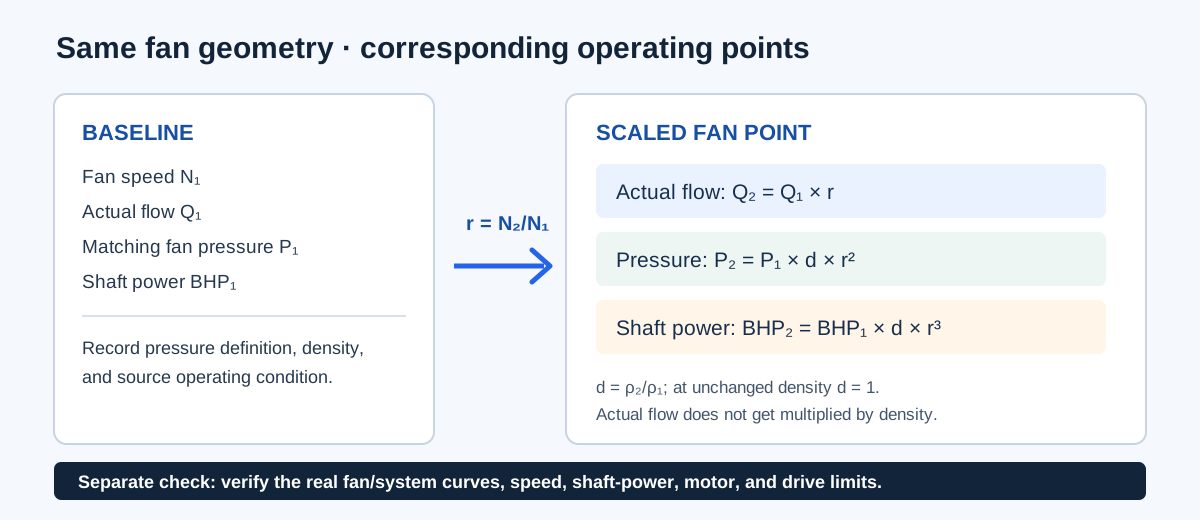
Fan laws estimate how a known operating point changes when the same fan runs at another speed. With fixed diameter and compatible dynamic similarity, actual volume flow follows the speed ratio; matching fan pressure follows the square of speed; and mechanical shaft power follows the cube. If inlet-air density also changes, pressure and shaft-power ratios include the ratio of new to baseline total-air density.
This is a comparison between corresponding fan points, not a complete prediction of a duct system. The result does not solve the fan curve against a fixed or changing system curve, establish that a controller can reach the target, or approve a speed or motor load. Do not confuse the fan laws with ACFM-to-SCFM conversion: the calculator scales actual volume flow with speed, while it reports total-air mass flow separately when density is entered.
| Quantity | Constant density | With explicit density ratio d = ρ₂/ρ₁ |
|---|---|---|
| Actual volume flow | Q₂/Q₁ = r | Q₂/Q₁ = r |
| Matching fan pressure | P₂/P₁ = r² | P₂/P₁ = d r² |
| Mechanical fan shaft power | BHP₂/BHP₁ = r³ | BHP₂/BHP₁ = d r³ |
| Total-air mass flow | 60 ρ Q at each state | 60 ρ Q at each state |
Choose a calculation mode and enter the matching point
The Fan Laws Calculator has four modes. Select the one that matches the known target and whether the inlet density changes. All modes keep fan diameter and geometry fixed.
- Performance at a new speed: enter baseline fan RPM, actual CFM, matching fan pressure, shaft BHP, and the new fan RPM.
- Speed for target airflow: enter the same baseline values and target actual CFM. The calculator derives the corresponding speed ratio.
- New speed with explicit densities: provide baseline and new total inlet-air density, new RPM, and confirm the same-fan similarity and airflow basis.
- Target actual airflow with explicit densities: provide the two densities and target actual CFM; the speed follows the target-to-baseline actual-flow ratio.
- For density modes, identify the fan, measurement or curve source, pressure definition, shaft-power basis, and density conditions. Use fan RPM rather than motor RPM when a belt changes the drive ratio.
| Input | Use this basis | Do not substitute |
|---|---|---|
| Airflow | Actual inlet volume flow in CFM | SCFM or a fixed mass-flow target |
| Pressure | The same fan total- or static-pressure definition at both points | TESP without an applicable fan-plane relationship |
| Power | Mechanical fan-shaft BHP | Motor nameplate HP or electrical kW |
| Density | Total air mass per actual inlet volume, lb/ft³ | Dry-air density or an assumed standard-air default |
Equations, variables, and assumptions
Let r be the new-to-baseline fan-speed ratio. In target-flow mode, the same ratio is target actual CFM divided by baseline actual CFM. Let d be the new-to-baseline total inlet-air density ratio. The explicit-density modes apply d to matching fan pressure and shaft power, but not to actual volume flow.
The classical relationships assume the same fan geometry and corresponding dynamically similar operating points. The cited ASHRAE treatment notes limitations such as Reynolds-number effects; efficiency changes, stall behavior, compressibility, diameter changes, and a nonhomologous system operating point are outside this calculator.
r = N₂ / N₁; d = ρ₂ / ρ₁
Q₂ = Q₁ r
P₂ = P₁ d r²
BHP₂ = BHP₁ d r³
ṁtotal = 60 ρ Q
| Symbol | Meaning | Unit or basis |
|---|---|---|
| N | Fan shaft rotational speed | RPM |
| Q | Actual inlet volume flow | CFM |
| P | Matching fan static or total pressure | in. w.g. |
| BHP | Mechanical fan shaft power | brake horsepower |
| ρ | Total inlet-air density | lb total air/ft³ |
| ṁtotal | Total-air mass flow | lb/h; 60 × ρ × CFM |
Independent worked example
Use a constructed fixed-diameter fan baseline of 1,750 RPM, 5,000 actual CFM, 2.5 in. w.g. matching fan pressure, and 3.5 BHP shaft power. Reduce speed to 1,400 RPM at unchanged density. The speed ratio is 1,400 / 1,750 = 0.8. Therefore Q₂ = 5,000 × 0.8 = 4,000 CFM; P₂ = 2.5 × 0.8² = 1.600 in. w.g.; and BHP₂ = 3.5 × 0.8³ = 1.792 BHP.
At the same speed ratio but with total inlet-air density changing from 0.075 to 0.060 lb/ft³, d = 0.8. Pressure becomes 2.5 × 0.8 × 0.8² = 1.280 in. w.g.; shaft power becomes 3.5 × 0.8 × 0.8³ = 1.4336 BHP. Actual flow remains 4,000 CFM. Baseline total-air mass flow is 60 × 0.075 × 5,000 = 22,500 lb/h; new total-air mass flow is 60 × 0.060 × 4,000 = 14,400 lb/h.
The first set independently matches the calculator’s constant-density example. The density case matches its explicit-density mode. The displayed answer may be rounded for presentation; the equations above retain the input precision.
r = 1,400 / 1,750 = 0.8; d = 0.060 / 0.075 = 0.8
Q₂ = 5,000 × 0.8 = 4,000 ACFM
P₂ = 2.5 × 0.8 × 0.8² = 1.280 in. w.g.
BHP₂ = 3.5 × 0.8 × 0.8³ = 1.4336 BHP
| Case | Independent result | Calculator example |
|---|---|---|
| Same density, 1,400 RPM | 4,000 CFM; 1.600 in. w.g.; 1.792 BHP | Same values in new-speed mode |
| Density 0.075 to 0.060 lb/ft³ | 4,000 ACFM; 1.280 in. w.g.; 1.4336 BHP | Same values in explicit-density mode |
| Total-air mass flow, density case | 22,500 to 14,400 lb/h | Reported as separate baseline and new mass flows |
Read the scaled result before using it
The output is a mathematical fan-law estimate from the entered baseline. Before changing a drive or selecting a setting, check the actual manufacturer fan curve, system resistance, operating region, speed limit, shaft-power limit, motor and drive ratings, and worst-case density. A changed filter, damper, duct resistance, or control condition can move the actual operating point away from the similarity path.
The density modes report total-air mass flow as 60 × density × actual CFM. That value is not dry-air mass flow, not a standard-volume conversion, and not a promise of constant mass delivery. An entered density and a confirmation checkbox are user-supplied assumptions; the calculator does not validate their sources.
| Question | What this calculation provides | Next evidence needed |
|---|---|---|
| Can the fan reach this flow? | A corresponding-point estimate | Applicable fan and system curves at the actual condition |
| Is the motor within its limit? | Fan shaft BHP estimate | Motor/drive ratings, efficiencies, controls, and operating limits |
| Does this airflow meet the load? | Actual volume-flow scaling | Project airflow requirement and compatible field or design basis |
| What is the standard airflow? | No SCFM conversion | Defined reference state and an appropriate air-property conversion |
Conclusion and limits
Use fan laws to compare corresponding operating points for the same fixed-geometry fan, with compatible pressure and shaft-power definitions. Use explicit density only when the actual method permits it and both total-air densities are documented. Then verify the proposed point against the real fan, system, motor, drive, and operating limits.
The relationships and limitations follow the cited ASHRAE 2024 fan-law treatment and Greenheck application guide. This article does not provide a universal fan selection, allowable speed, energy-savings guarantee, or compliance determination.
FAQs
Do fan laws guarantee the new operating point is attainable? No. The fan and system curves must support the corresponding point.
Does density multiply volume flow? No. In the implemented similarity model, volume flow scales with speed ratio while pressure and shaft power include density.
Can I use motor RPM, electrical kW, or SCFM in place of the stated inputs? Only with an explicit compatible conversion and boundary.