
Balance and vibration are different assessments
Residual unbalance is a rotor quantity expressed as a permissible moment or equivalent tolerance mass at a correction radius. Vibration severity is a measured response at a location, support, axis, quantity, frequency span, and operating condition. A rotor can satisfy a balance tolerance while the installed fan still has aerodynamic excitation, resonance, misalignment, looseness, or support problems.
The calculator keeps three methods separate: rigid-rotor residual balance, assembled factory filter-in vibration, and installed overall filter-out vibration. They share a page because they concern the same equipment, but their inputs and criteria cannot be exchanged.
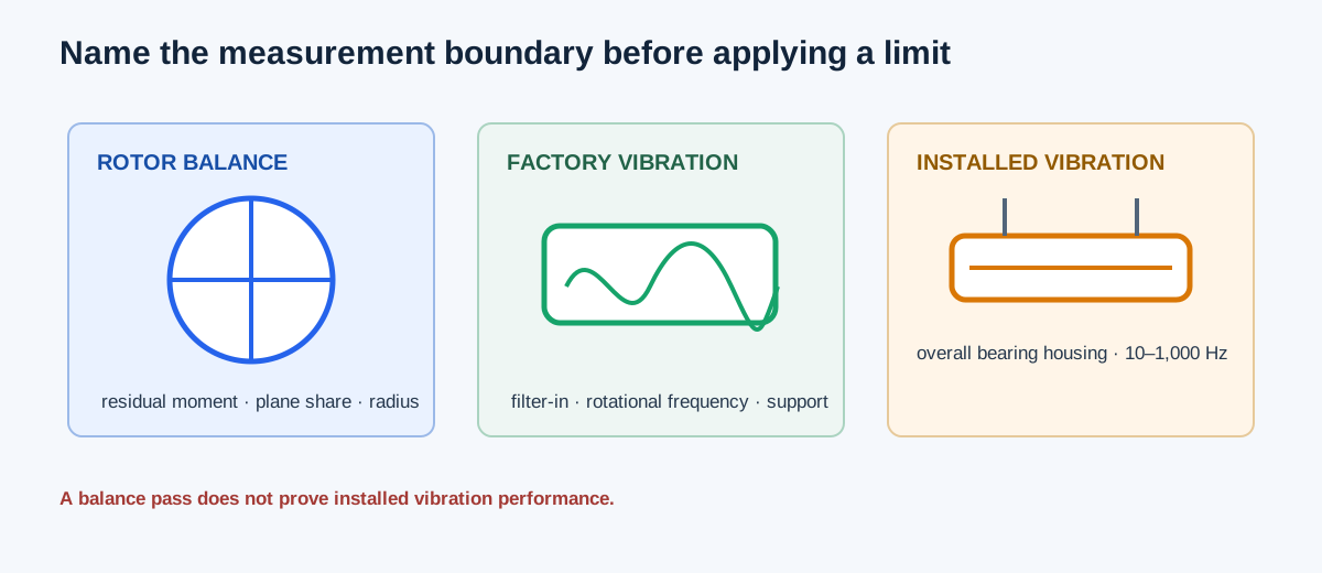
| Method | Measured or calculated quantity | Boundary |
|---|---|---|
| Rotor balance | Residual unbalance moment and plane allocation | Rigid rotor, service RPM, correction-plane specification |
| Factory vibration | Filter-in velocity at rotational frequency | Assembled fan, support class, peak/RMS, source limit |
| Installed vibration | Overall bearing-housing velocity | Rated operating point, support/axis, 10–1,000 Hz coverage |
Choose the method and document the measurement basis
For residual balance, enter the agreed BV category, rigid-rotor scope, rotor mass in lbm, service or design RPM, correction-plane count, each plane’s documented allocation share, radius, and measured residual moment. Shares must sum to one; the calculator allocates the total tolerance instead of granting every plane the full rotor tolerance.
For factory or installed vibration, enter the agreed category and edition, peak or RMS velocity quantity, input unit, test basis, support class for each location, and one row per distinct location/axis. Installed overall readings must cover at least 10–1,000 Hz. BV1 and BV2 have no standard shutdown number in this implementation, so a documented historical or project shutdown value is required for the installed method.
| Input | Why it matters |
|---|---|
| BV category and edition | Defines the selected grade and table cell |
| Peak or RMS | Uses a different source limit; no automatic √2 conversion |
| Rigid/flexible support | Selects a different support column |
| Factory or installed basis | Determines filter-in versus overall filter-out criteria |
| Location and axis IDs | Prevents averaging separate readings |
Independent residual-balance example
Use a BV3 rigid rotor with G = 6.3 mm/s, 10 lbm rotor mass, and 1,800 RPM service speed. Angular speed is ω = 2π × 1,800/60 = 188.495559 rad/s. Specific permissible unbalance is e = G/ω = 0.033422538 mm, or 33.422538 µm. The calculator’s I-P moment conversion gives a total permissible residual unbalance of 0.210535673 oz-in.
Allocate 50% to each of two correction planes. Each plane limit is 0.105267836 oz-in. With measured residuals of 0.100 and 0.120 oz-in, plane 1 has 0.005267836 oz-in margin and plane 2 has −0.014732164 oz-in margin. One plane exceeds its allocated limit. The equivalent tolerance mass at a 5 in radius is the plane limit divided by radius; it does not provide a correction angle or influence coefficient.
ω = 2π × 1,800/60 = 188.495559 rad/s
e = 6.3/ω = 0.033422538 mm = 33.422538 µm
Total permissible residual = 0.210535673 oz-in
Plane limit = 0.210535673 × 0.50 = 0.105267836 oz-in
Plane 1 margin = 0.105267836−0.100 = 0.005267836 oz-in
Plane 2 margin = 0.105267836−0.120 = −0.014732164 oz-in
| Result | Independent value | Calculator display |
|---|---|---|
| Angular speed | 188.495559 rad/s | 188.495559 rad/s |
| Total permissible residual | 0.210535673 oz-in | 0.210535673 oz-in |
| Each 50% plane limit | 0.105267836 oz-in | 0.105267836 oz-in |
| Plane 1 margin | 0.005267836 oz-in | 0.005267836 oz-in |
| Plane 2 margin | −0.014732164 oz-in | −0.014732164 oz-in |
Independent installed-vibration example
Use BV3 RMS installed readings entered in inches per second: rigid drive horizontal 0.20 in./s, flexible non-drive vertical 0.30 in./s, and rigid drive axial 0.40 in./s. The calculator converts with 25.4 mm per inch to 5.08, 7.62, and 10.16 mm/s. The BV3 RMS alarm limits are 7.1 mm/s for rigid support and 11.8 mm/s for flexible support; the BV3 rigid RMS shutdown limit is 9.0 mm/s.
The first reading is below alarm. The flexible reading is below its 11.8 mm/s alarm. The rigid axial reading is 10.16 mm/s, so it reaches both the 7.1 mm/s alarm and the 9.0 mm/s shutdown threshold. The output identifies the highest normalized reading; it does not diagnose the cause or average the readings into one value.
0.20 in./s × 25.4 = 5.08 mm/s
0.30 in./s × 25.4 = 7.62 mm/s
0.40 in./s × 25.4 = 10.16 mm/s
Rigid BV3 RMS: alarm = 7.1 mm/s; shutdown = 9.0 mm/s
Flexible BV3 RMS: alarm = 11.8 mm/s
| Point | Converted reading | Criterion |
|---|---|---|
| Rigid drive horizontal | 5.08 mm/s | Below 7.1 mm/s alarm |
| Flexible non-drive vertical | 7.62 mm/s | Below 11.8 mm/s alarm |
| Rigid drive axial | 10.16 mm/s | At/above 7.1 alarm and 9.0 shutdown |
Interpret a limit result and investigate the system
A balance pass says the entered residual moments fit the selected plane allocations. It does not prove the assembled fan or installation is vibration-free. A factory pass applies to the stated assembled filter-in test basis. An installed pass applies to the measured overall band and selected support/axis criteria; it does not prove the absence of a developing fault.
When a reading reaches alarm or shutdown, follow the governing manufacturer and project procedure. Check operating speed, balance, alignment, bearings, belt or coupling, foundation, isolation, fasteners, aerodynamic conditions, resonance, and measurement setup. Preserve the location, axis, quantity, frequency span, operating condition, and trend so a repeat measurement remains comparable.
| Finding | Next check |
|---|---|
| Residual plane exceeds limit | Confirm plane share, radius, service RPM, and balancing method |
| Factory reading exceeds limit | Confirm filter-in basis, support, quantity, speed, and assembly condition |
| Installed alarm | Follow corrective-action procedure and repeat the same location/axis basis |
| Installed shutdown | Apply the documented immediate-action or shutdown procedure |
| Single high point | Inspect that location and verify sensor mounting before averaging anything |
FAQs
Can I convert broadband peak to RMS with √2? No. The calculator uses the measured quantity and matching source column; it does not apply a sinusoidal conversion to broadband readings.
Can I average all bearing readings? No. Location, axis, support, and normalized ratio matter. The critical reading is retained rather than hidden by an average.
Does balance tolerance give the correction weight? No. Equivalent tolerance mass is a moment divided by radius. Phase, influence coefficients, correction angle, and the actual balancing procedure are separate.
Does an alarm identify the fault? No. It identifies a comparison against the selected limit. Diagnosis requires equipment history, spectrum or additional measurements, and field inspection.
Conclusion and limits
Start by naming the measurement boundary: rotor residual balance, assembled factory vibration, or installed overall vibration. Keep the quantity, support, axis, frequency range, speed, and source limits attached to each result, then investigate trends and physical causes separately.
The AMCA 204-20 tables and calculator implementation support the stated arithmetic and distinctions. They do not diagnose a fault, prescribe balancing weights or shutdown actions beyond the selected source procedure, or certify an installed fan.