
Three geometry tasks that should stay separate
A centered rectangular transition changes width and/or height while keeping the end centers aligned. An offset rectangular transition changes the end center position and evaluates four signed wall displacements. A two-elbow offset uses actual bend radii, tangent tails, a middle gap, and a connector cut allowance to move a constant-section duct and return the outlet parallel to the inlet.
The related calculators use different input contracts and formulas. Do not use the centered transition length as a two-elbow cut length, or use a single resultant offset as if it described every rectangular wall. Each result is geometric and preliminary; it does not provide pressure coefficients, seam allowances, or fabrication approval.
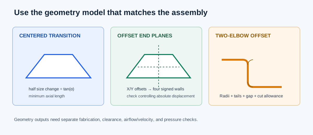
| Task | Required geometry | Primary result |
|---|---|---|
| Centered transition | Start/end clear width and height, selected per-wall angle | Minimum axial length or wall-angle check |
| Offset rectangular transition | Start/end clear dimensions, signed X/Y center offsets, per-wall angle | Four signed/absolute wall angles and controlling length |
| Two-elbow offset | Equal bend angle, radii, tangent tails, gap or resultant rise/over | Cut length, axial run, centerline offset, developed length |
Use the rectangular transition modes
Enter start and end clear inside width and height in inches and a selected maximum wall angle measured from the original duct axis. The centered minimum-length mode splits each size change across two walls and uses the larger half-change as the controlling displacement. The available-length check calculates both width-side and height-side wall angles; the included angle is not the same criterion.
For an offset transition, confirm parallel end planes, fixed untwisted axes, signed center offsets, and a per-wall angle criterion. Positive X is right and positive Y is up in the documented end view. The calculator evaluates left, right, bottom, and top signed displacements separately. A zero included angle can coexist with a wall-angle failure when parallel offset walls are both tilted from the original axis.
The result is a geometric projection. It does not calculate area change pressure recovery, fitting loss, a flat pattern, seam allowance, panel cutting layout, installed outside clearance, or current code compliance.
Centered transition: Lmin = max(|W₂−W₁|/2, |H₂−H₁|/2) / tan(α)
Offset wall displacements:
Left/right = X ∓ (W₂−W₁)/2
Bottom/top = Y ∓ (H₂−H₁)/2
Wall angle = atan(displacement/L)
| Input | Meaning | Boundary |
|---|---|---|
| Start/end dimensions | Clear inside rectangular openings | No sheet, liner, or outside envelope correction is inferred |
| X/Y center offsets | Signed end-center movement | Fixed view and parallel end-plane basis |
| Maximum wall angle | Per-wall tilt from original axis | Not an included angle or universal standard |
| Available length | Axial separation of end planes | Not sloping center-to-center distance |
Independent offset-transition example
Use start 16 × 12 in, end 10 × 8 in, signed center offsets X = +3 in and Y = −2 in, and a 15° per-wall limit. The half-width change is (10−16)/2 = −3 in and the half-height change is (8−12)/2 = −2 in. The four signed wall displacements are left 3−(−3)=6 in, right 3+(−3)=0 in, bottom −2−(−2)=0 in, and top −2+(−2)=−4 in.
The largest absolute displacement is 6 in, so minimum axial length is 6/tan(15°) = 22.3923 in. At that length, the left wall is 15°, the top wall is about 10.1281°, and the right and bottom walls are 0°. The calculator returns the same controlling length and individual wall-angle results. A 24 in available length therefore leaves 1.6077 in axial margin in this constructed case.
Left = 3 − (10−16)/2 = 6 in
Right = 3 + (10−16)/2 = 0 in
Bottom = −2 − (8−12)/2 = 0 in
Top = −2 + (8−12)/2 = −4 in
Lmin = 6/tan(15°) = 22.3923 in
| Wall | Signed displacement | Angle at Lmin |
|---|---|---|
| Left | 6 in | 15.0000° |
| Right | 0 in | 0.0000° |
| Bottom | 0 in | 0.0000° |
| Top | −4 in | −10.1281° |
| Controlling minimum length | 6/tan(15°) | 22.3923 in |
Independent two-elbow offset example
Use two opposing 90° elbows with 6 in centerline radius each, inward diagonal tangent tails totaling 2 in, outer parallel tails totaling 3 in, total straight-piece insertion allowance 1 in, and required centerline offset 20 in. The two arcs contribute R(1−cosθ) = (6+6)(1−0) = 12 in of offset. The remaining diagonal centerline displacement is 20−12 = 8 in; after subtracting the 2 in inward tails, the installed straight gap is 6 in.
The straight-piece cut length is gap + insertion allowance = 6+1 = 7 in. In the existing 90° model, the axial end-to-end run is 15 in: the two arc projections contribute 12 in and the outer parallel tails contribute 3 in; the inward diagonal tails contribute to the offset construction and do not add an additional axial projection at 90°. Use the calculator’s stated geometry contract rather than replacing it with a generic triangle.
For the same inputs, the documented result is 7 in straight-piece cut, 20 in centerline offset, 15 in axial end-to-end run, and 29.8496 in developed centerline length. This is a fitting-drawing arithmetic example; confirm actual radii, tangent tails, connector engagement, and shop orientation before cutting.
Offset O = R(1−cosθ) + (G+B)sinθ
Cut length = G + insertion allowance
For the constructed 90° case: O = 12 + (6+2) = 20 in; cut = 6+1 = 7 in
| Output | Independent basis | Calculator display |
|---|---|---|
| Centerline offset | 12 + 6 + 2 | 20 in |
| Installed straight gap | 20 − 12 − 2 | 6 in |
| Straight-piece cut | 6 + 1 insertion allowance | 7 in |
| Axial run | Existing 90° arc/tail projection model | 15 in |
| Developed centerline length | Arc + gap + tails | 29.8496 in |
Move the geometry into the next review
Transfer the selected clear dimensions and offsets to the actual drawing. Check connection planes, liner, insulation, supports, access, turning clearance, and whether the chosen angle criterion applies to the fabrication standard. For a two-elbow offset, verify each fitting’s centerline radius, tangent tails, seam orientation, connector engagement, and whether the rise/over coordinate view matches the shop drawing.
Then evaluate airflow area and velocity change, fitting and transition pressure loss, acoustic consequences, and the complete critical path separately. A correct geometric layout can still fail an installation envelope or pressure budget.
| Check | Question |
|---|---|
| Geometry | Do the clear end dimensions and signed offsets match the drawing? |
| Fabrication | Are radii, tangent tails, seams, connector engagement, and cut allowances documented? |
| Installation | Does the outside assembly fit with insulation, supports, and access? |
| Performance | Are area/velocity change and pressure loss included in the system model? |
FAQs
Is a centered transition length a fabrication cut length? No. It is the minimum axial separation from the selected per-wall angle criterion.
Does rise/over direction rotate the rectangular end opening? No. It describes signed transverse movement in a fixed coordinate drawing; it is not connector clocking or section rotation.
Can the two-elbow result be used without the fitting drawing? No. Actual radii, tangent tails, insertion allowance, and equal-opposing-bend assumptions are required.
Conclusion and limits
Choose the centered transition, offset transition, or two-elbow model that matches the physical assembly. Keep clear geometry, signed offsets, per-wall angle, bend dimensions, and connector allowances visible, then carry the result into fabrication, installation, and pressure checks.
The calculator outputs are geometry models under their stated assumptions. They do not provide a shop drawing, universal angle limit, fitting pressure coefficient, seam allowance, structural check, or code approval.