
A duct sound path is a chain of separate boundaries
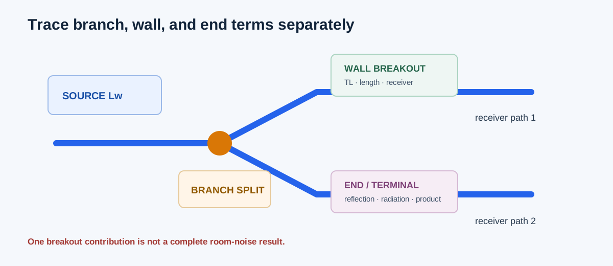
Branch division, duct-wall breakout, and end reflection answer different acoustic questions. A branch can divide source sound power between paths; a duct wall can radiate sound to a nearby receiver; an end or opening can reflect or transmit energy according to its termination. They need compatible source planes, octave bands, geometry, construction, and receiver or termination models.
This guide focuses on tracing the wall-breakout contribution and keeping it separate from branch, silencer, terminal, room, and end-reflection effects. A supported breakout result is one path contribution. It is not a complete room NC, RC, NR, dBA, or compliance result.
| Term | Boundary | Do not substitute |
|---|---|---|
| Sound power Lw | Source energy at a defined duct or fan plane | Receiver sound pressure Lp |
| Transmission loss TL | Source-matched wall construction and frequency | Generic material loss |
| Breakout contribution | One duct wall and radiating length | Whole-room noise |
| End reflection | Termination and incident wave condition | Wall breakout loss |
| Branch division | Flow/sound path and junction basis | A simple CFM split without acoustic data |
Enter the actual construction and eight octave bands
Confirm that the selected wall profile or custom transmission-loss rows match the actual duct shape, dimensions, gauge, seam, lining, specimen length, and frequency range. The calculator preserves missing, bounded, and parenthesized source cells as unsupported. It does not interpolate a material coefficient or replace a missing band with zero.
Enter actual radiating length and receiver distance in feet, an evidenced confinement correction from 0 to 6 dB, and each of the eight octave rows at 63 through 8,000 Hz: source sound power, attenuation rate, separate path loss, and allocated breakout budget. Confirm that the near-line receiver approximation fits the project before using the result.
| Step | Enter or confirm | Reason |
|---|---|---|
| 1 | Construction profile and normalized TL | Defines the wall transmission boundary |
| 2 | Radiating length, receiver distance, confinement | Defines the selected receiver approximation |
| 3 | Eight source levels and attenuation rates | Carries source energy through the actual run |
| 4 | Separate path losses and budgets | Keeps ceiling/path effects from being counted twice |
| 5 | Support flags and margins | Prevents a partial table from becoming a complete room claim |
Independent 125 Hz breakout example
Use the constructed ASHRAE Example 4 geometry: a 24 × 24 in, 22 gauge rectangular duct, 25 ft radiating length, and a receiver 5 ft away. At 125 Hz, source sound power is 85 dB re 1 pW, normalized transmission loss is 23 dB, and attenuation is 0.2 dB/ft. The duct area is 24 × 24 = 576 in² and perimeter is 2(24+24) = 96 in.
Set k = α ln(10)/10 = 0.2 ln(10)/10. The continuously attenuated effective length is [1−exp(−kL)]/k = 14.847925 ft. The implemented equations give breakout sound power 76.726958 dB, near-line receiver correction −15.940599 dB, and receiver contribution 60.786359 dB. Against a 60 dB allocated budget, the margin is −0.786359 dB, so this band exceeds its allocation.
k = 0.2 × ln(10)/10
L* = [1−exp(−k×25)]/k = 14.847925 ft
Lw,out = 76.726958 dB re 1 pW
Receiver correction = −15.940599 dB
Lp = 76.726958 − 15.940599 = 60.786359 dB
Margin = 60.000000 − 60.786359 = −0.786359 dB
| Result | Independent value | Calculator display |
|---|---|---|
| Duct area | 576 in² | 576 in² |
| Duct perimeter | 96 in | 96 in |
| Effective length | 14.847925 ft | 14.847925 ft |
| Breakout sound power | 76.726958 dB | 76.726958 dB |
| Receiver contribution | 60.786359 dB | 60.786359 dB |
| Budget margin | −0.786359 dB | −0.786359 dB |
Read the result across the path
A supported octave band means the selected construction, source level, attenuation, geometry, and receiver approximation produced a finite result under the stated model. A positive budget margin means that one breakout contribution is below its assigned band budget. It does not mean the complete room or duct system passes.
A source band can remain unsupported when a table cell is missing or bounded. A partial result should lead to additional source data or a different applicable acoustic model. Do not fill the gap with an adjacent frequency, generic material rule, or zero attenuation.
| Finding | Next check |
|---|---|
| Band exceeds budget | Check source, TL, attenuation, radiating length, separate path loss, and confinement basis |
| Band unsupported | Obtain matching construction data or use another documented model |
| All breakout bands pass | Add fan, branch, terminal, silencer, end, room, and background paths |
| Room criterion is needed | Convert compatible source power to receiver pressure and use a complete octave-band model |
How branch and end terms fit around breakout
At a branch, sound power division must follow a compatible junction and path model. Airflow division alone does not determine the acoustic split. After a branch, each path can have its own duct length, fittings, lining, breakout wall, terminal, and receiver. Sum or compare contributions only after their source and receiver references are compatible.
At an end or termination, reflection and radiation depend on the opening geometry, incident field, and termination model. Do not subtract an end-reflection loss from a wall-breakout result unless the source method defines that relationship. Keep separate losses on the path diagram so the same attenuation or ceiling effect is not counted twice.
| Path stage | Record |
|---|---|
| Source | Lw, frequency, fan/duct reference plane |
| Branch | Path split method and each downstream branch |
| Straight run | Length, attenuation, fittings, and pressure/sound data |
| Wall breakout | Construction TL, radiating length, receiver basis |
| End/terminal | Termination model, product data, reflection or radiation |
| Receiver | Lp reference, room/path loss, background, criterion |
FAQs
Does a low breakout result prove a quiet room? No. Fan, terminal, branch, structure, background, end, flanking, and reverberant contributions may still govern.
Can I use ordinary wall TL as breakout TL? No. The input must use the normalized breakout transmission-loss reference expected by the selected method.
Can I extend a source table to a missing octave band? No. Missing and bounded cells remain unsupported in the calculator.
Can I divide total lined-duct insertion loss by length to create α? Only when a documented model supports that conversion for the actual construction and band. A total product loss is not automatically a constant dB/ft rate.
Conclusion and limits
Trace one source-to-receiver contribution at a time. Keep branch division, wall breakout, end reflection, terminal self-noise, and room/background terms on their own boundaries, and preserve unsupported frequency cells instead of manufacturing a complete result.
The implemented equations and cited ASHRAE method describe one airborne duct-wall breakout contribution under a selected near-line receiver model. They do not calculate total room noise, structural vibration, NC/RC/NR/dBA, or installation compliance.