
Blade-pass frequency locates a repeating event
Blade-pass frequency (BPF) is the rate at which uniformly spaced rotor blades pass a fixed point. It identifies candidate frequency locations in a fan spectrum. It does not provide sound pressure, sound power, resonance amplitude, bearing condition, or a fault diagnosis.
Keep rotor blade count, fan shaft RPM, shaft rotational frequency, BPF, harmonics, VFD electrical frequency, motor poles, and stationary vane count separate. The calculator models one rotor with an established shaft speed and displays the fundamental plus the selected harmonic range.
| Quantity | Formula | Meaning |
|---|---|---|
| Shaft rotation | RPM/60 | One revolution per second |
| Fundamental BPF | blades × RPM/60 | One blade-passage event cycle |
| Harmonic k | k × BPF | Integer multiple of the fundamental |
| BPF period | 1/BPF seconds | Time between fundamental cycles |
Choose the speed mode and enter rotor inputs
For a known-speed calculation, enter a positive whole rotor blade count, the highest harmonic order from 1 through 10, and fan shaft RPM. Zero RPM is accepted as a stopped-rotor state and produces zero frequency without a finite passage period.
For a target-frequency calculation, enter the target fundamental BPF and solve RPM = target BPF × 60/blades. The target is always the fundamental; the selected harmonic display does not change the inversion. For a speed range, enter minimum and maximum fan shaft RPM and read the endpoint frequency envelope. The range mode does not invent a center operating speed or duty-cycle average.
| Mode | Enter | Read |
|---|---|---|
| Known speed | Blade count, harmonic order, shaft RPM | BPF, shaft frequency, period, harmonics |
| Target BPF | Blade count, harmonic order, target fundamental Hz | Required shaft RPM and harmonic locations |
| Speed range | Blade count, harmonic order, min/max RPM | Minimum and maximum BPF and harmonic envelope |
Independent known-speed example
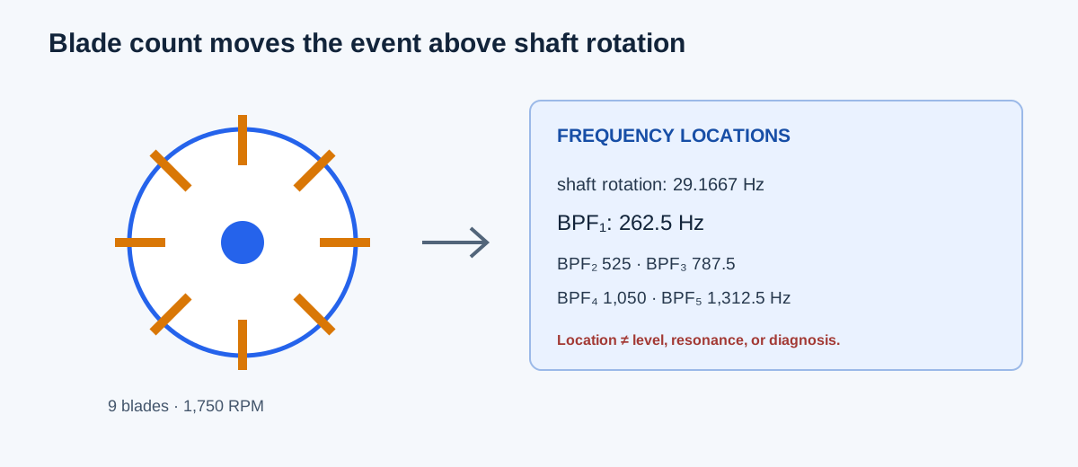
Use nine rotor blades, 1,750 RPM, and harmonics through order 5. Shaft rotational frequency is 1,750/60 = 29.1666667 Hz. Fundamental BPF is 9 × 29.1666667 = 262.5 Hz. Blade events occur at 15,750 passes/min, and the fundamental period is 1/262.5 × 1,000 = 3.8095238 ms. Harmonics are 525, 787.5, 1,050, and 1,312.5 Hz.
The calculator displays the same values at its configured precision. The result says where periodic components may appear; it does not say whether a component is measurable or objectionable.
Shaft Hz = 1,750/60 = 29.1666667 Hz
BPF = 9 × 1,750/60 = 262.5 Hz
Passes/min = 262.5 × 60 = 15,750
Period = 1,000/262.5 = 3.8095238 ms
Harmonic k = k × 262.5 Hz
| Result | Independent value | Calculator display |
|---|---|---|
| Shaft rotational frequency | 29.1666667 Hz | 29.166667 Hz |
| Fundamental BPF | 262.5 Hz | 262.5 Hz |
| Blade passes per minute | 15,750 | 15,750 |
| BPF period | 3.8095238 ms | 3.809524 ms |
| Fifth harmonic | 1,312.5 Hz | 1,312.5 Hz |
Independent target and speed-range examples
For seven blades and a target fundamental BPF of 350 Hz, required shaft speed is 350 × 60/7 = 3,000 RPM. The fifth harmonic would be 1,750 Hz. For nine blades over a 900–1,800 RPM speed range, minimum BPF is 9 × 900/60 = 135 Hz and maximum BPF is 9 × 1,800/60 = 270 Hz.
A measured spectrum should be compared with the actual speed at the time of measurement. A variable-speed fan can move BPF and its harmonics through a band; the endpoint envelope does not establish how long the fan operates at any frequency.
Target RPM = target BPF × 60/blades = 350 × 60/7 = 3,000 RPM
Range minimum BPF = 9 × 900/60 = 135 Hz
Range maximum BPF = 9 × 1,800/60 = 270 Hz
| Case | Independent value | Calculator display |
|---|---|---|
| 7 blades, 350 Hz target | 3,000 RPM | 3,000 RPM |
| 9 blades, 900 RPM minimum | 135 Hz BPF | 135 Hz BPF |
| 9 blades, 1,800 RPM maximum | 270 Hz BPF | 270 Hz BPF |
Compare a frequency location with the actual spectrum
Record fan shaft speed, blade count, measurement location, sensor and bandwidth, operating condition, and any nearby structural or aerodynamic source. Compare the calculated BPF and harmonics with a compatible spectrum. A coincident peak can support a follow-up hypothesis, but amplitude, coherence, sidebands, speed order tracking, resonance, and trend are needed for diagnosis.
Check the fan, drive, supports, bearings, inlet/outlet geometry, dampers, and system operating point before changing speed. A target RPM selected only to move a frequency can create a new aerodynamic, mechanical, power, or control problem.
| Evidence | Purpose |
|---|---|
| Actual shaft RPM | Align the calculated event with the measured state |
| Blade and vane geometry | Separate rotor blade events from stationary interactions |
| Spectrum and level | Determine whether the frequency is present and significant |
| Speed trend/order data | Separate speed-related components from fixed resonances |
| Fan/system and mechanical checks | Investigate the cause before changing operation |
FAQs
Is BPF the same as VFD output frequency? No. VFD electrical Hz is an electrical/control quantity; BPF uses fan shaft RPM and rotor blade count.
Does every harmonic have equal amplitude? No. The calculator only locates integer multiples. Actual amplitudes depend on blade spacing, flow, geometry, structure, and measurement path.
Can BPF alone diagnose a bearing fault? No. It is a candidate frequency location, not a fault signature or severity measurement.
Does zero RPM have a finite blade-pass period? No. A stopped rotor has no repeating blade passage, so the calculator omits the period.
Conclusion and limits
Use BPF to convert blade count and fan shaft speed into candidate event frequencies, then compare those locations with a measured spectrum under the same operating condition. Keep frequency location separate from level, resonance, diagnosis, and permitted speed.
The calculator implements the stated blade-event relationship for a single uniformly repeated rotor. It does not model unequal blade spacing, rotor-stator interaction, sound level, vibration severity, resonance, or an allowable operating condition.